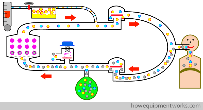
We will discuss the following aspects. Please scroll down and start reading.
- Basic circle system
- Positive pressure ventilation
- Advantages of circle system
- Extra details on some of the components

Everyone wants happiness. However, according to psychologists, many of us think in certain ways which can prevent us from being happy. One may not even realise that one is thinking in such ways. The free website at the link below explains the concept of “Happy Thinking” which is about thinking in ways that help one to be happy. Once you discover “Happy Thinking” you will find yourself becoming a happier person. The website is completely free.

Let us make a circle breathing system !
A “breathing system” is an arrangement of tubes and other components that transports gases between the anaesthetic machine and the patient. A very common breathing system used in anaesthesia is the “circle breathing system” and I will introduce its functioning to you. This breathing system has many advantages which we will discuss later. To make things easier, I will from now on, shorten “the circle breathing system ” to “circle system “.
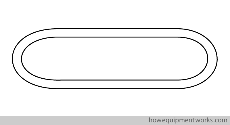
I think a good way to understand how the circle system works is to “construct” one, step by step. Let us begin “making” our circle system by drawing a circular tube.
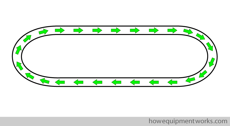
The gases inside the circle system go around in a circular way.
Let us start adding parts to our circle, in a step by step way. The first part I would like to add to the circle is a patient !
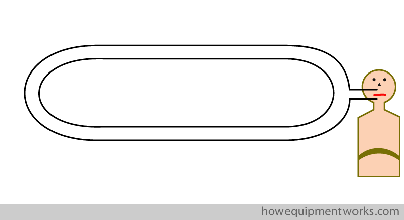
However, though we have connected the patient to the circle, he will unfortunately not be able to breath in or out from it. This is because the circular tube is made of a non stretchable material and therefore it cannot expand to accept the patient’s expiration, and nor can it contract when the patient tries to inspire from it.
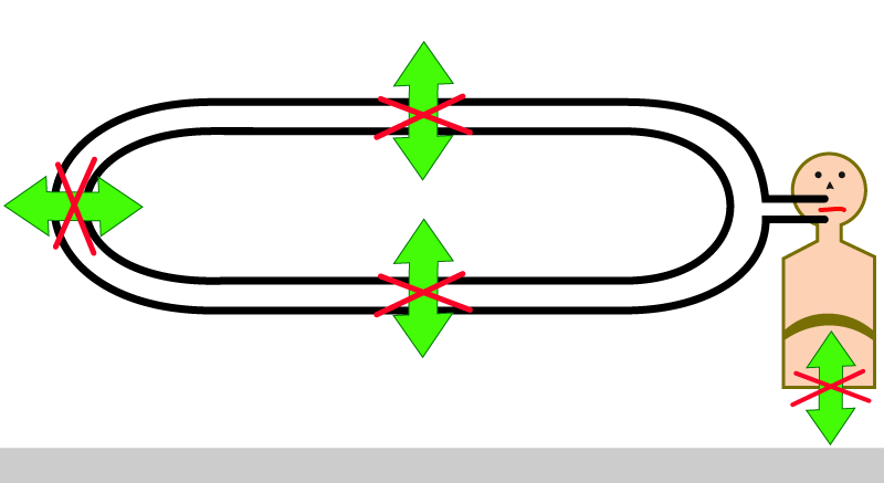
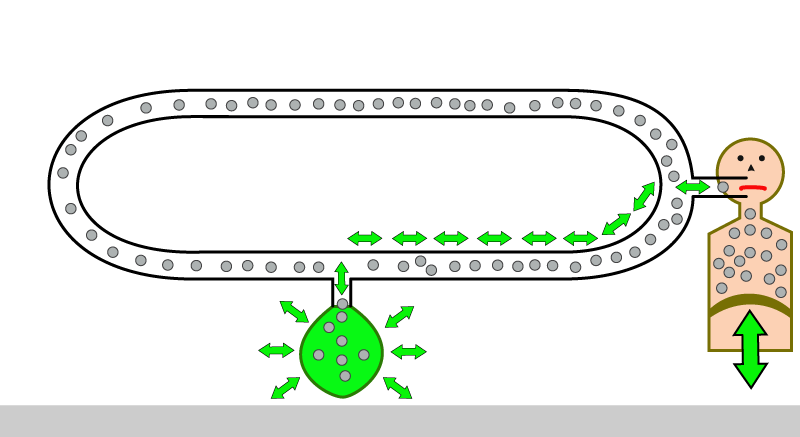
To allow the patient to breath in and out, we attach a flexible bag ( called reservoir bag ) to the circle system. Now the patient can breath, through the tubes, into and out of the flexible reservoir bag.
However, if we leave our patient like this, he will not survive, since we are forgetting to give him something vital for life. We need to urgently give our patient oxygen ! The oxygen (and other gases) come out of the flow meters of your anaesthetic machine. The flow meters allow you to control the flow of the various gases that you supply to your patient. The total flow of gases coming out of the flow meters is called ” total fresh gas flow” or more commonly , simply referred to as, “fresh gas flow”.
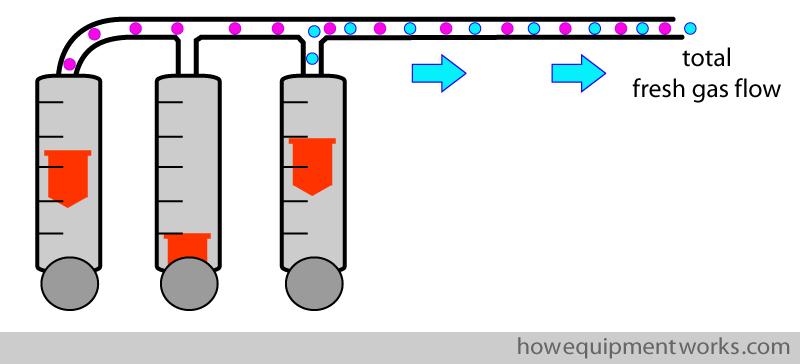
So, to keep our patient alive, we supply fresh gas flow ( containing oxygen, shown as blue dots ) from the flow meters into the circle system.
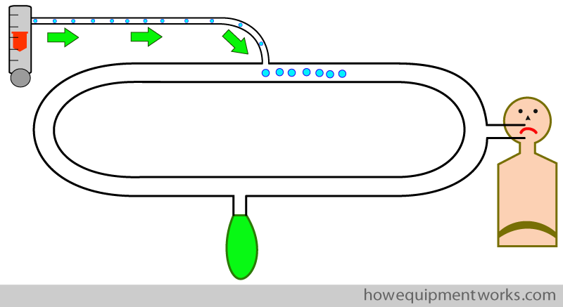
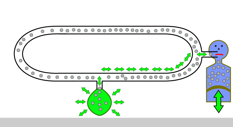
Unfortunately there still is a problem. Though we are giving oxygen into the circle, it is not reaching the patient! The reason for this is that he is breathing in his own expired air (shown in grey) which of course does not have much oxygen. This breathing of his own oxygen depleted air will make him hypoxic !
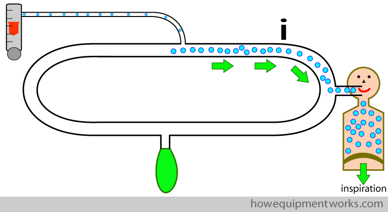
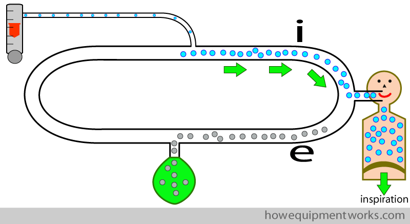
As I will explain to you, the solution is to “force” the patient to inspire from one section of the circle and to expire into a different section of the circle. I will explain later how we “force” the patient to do this. In the diagram below, we ” force ” the patient to inspire from the circle system tubing labelled as ” i “.
We then “force” our patient to expire to a different part of the circle system ( the part labelled “e “). I.e. the inspiratory pathway and the expiratory pathway are separate.
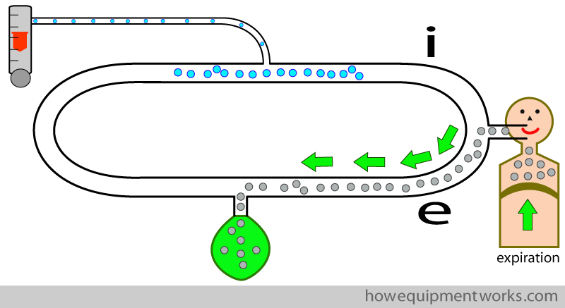
In this way, the patient will inspire oxygen rich fresh gas rather than the gases he just expired. I will next explain how we will “force ” the patient to breath the way we just discussed.
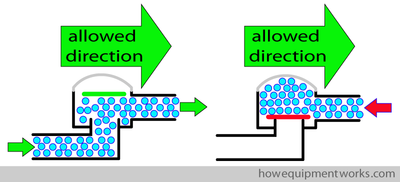
We ” force ” the patient to inspire from one part of the circle, and expire into the other part of the circle, using what are called “one way valves “. As their name suggests, these valves allow gas to pass one way, and not the other way. The valve has a disc that opens only in one direction, allowing gases to only go in that direction. In the example below, the one way valve is designed to allow flow in the direction of the green arrow and not allow flow to go in the opposite direction..
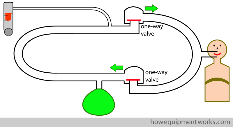
We add two one way valves into the circle system as shown below. One allows flow only towards the patient and the other allows flow only away from the patient.
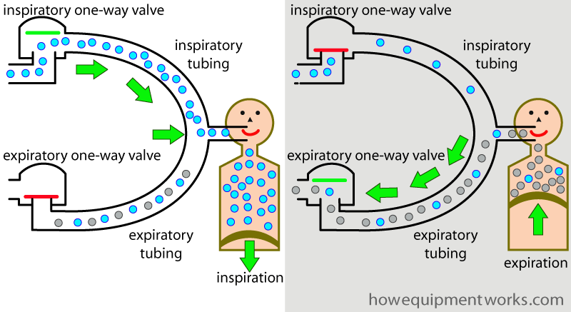
During inspiration, the valve labelled ” expiratory one way valve ” closes, preventing the patient from inspiring the gases he just breathed out. On the other side, the valve labelled ” inspiratory one way valve opens, letting the patient inspire gases rich with oxygen. The tubing from the inspiratory one way valve to the patient carries only inspiratory gases, and we can therefore call it the “inspiratory tubing “.
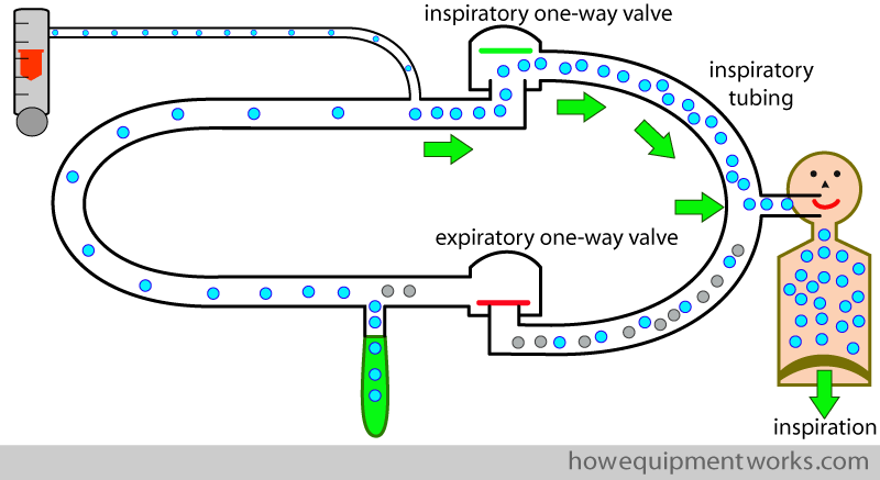
During expiration, the reverse happens. The inspiratory one way valve closes, preventing the expired gases going into the inspiratory tubing. Instead, the valve labelled “expiratory one way valve” opens, letting expired gases go via the tubing between it and the patient. The tubing between the patient and the expiratory one way valve carries only expired gases, so we can therefore call it the “expiratory tubing “.
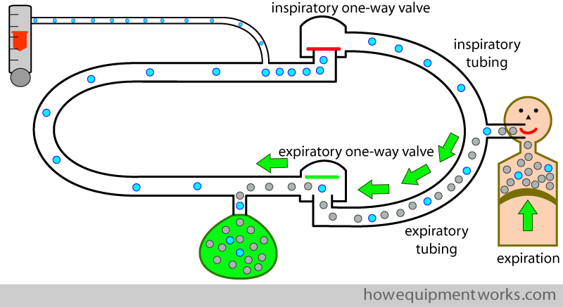
So now our patient is happy. Due to the inspiratory and expiratory one way valves, our patient correctly inspires from the inspiratory tubing and expires into the expiratory tubing.
Now here is a small distraction. I am sure that you have heard about Leonardo Da Vinci. Just in case you did not know, he is the one who painted the Mona Lisa. If you are very interested in things historical, you may want to click on the image below. It will take you to a page where I have discussed the possibility that Leonardo Da Vinci, who lived 500 years ago, may have understood the concepts we have just discussed ! If you visit that page, please do remember to come back here ! Do also let me know what you think about it. Thank you.
Pressure Limiting outflow valve
However, we discover another problem. We find that the reservoir bag is mysteriously getting bigger and bigger.
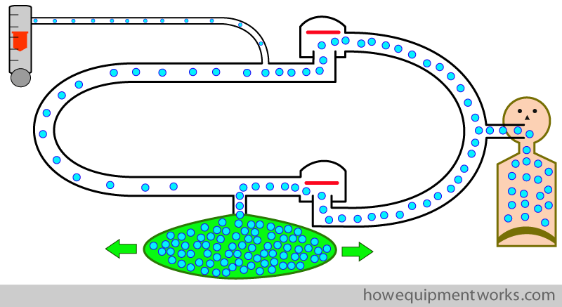
Ultimately the reservoir bag bursts !
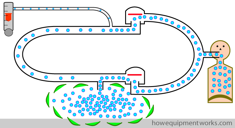
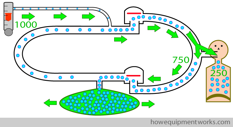
So why did this happen ? The reason is that we normally give more oxygen (and other gases) than the patient needs. For example, in the setting below, we are giving the patient 1000 ml of oxygen per minute. Of this, in our example, suppose the patient takes only 250 mL of oxygen per minute. That means that every minute, there is an excess of 750 ml of oxygen. The only place that this excess oxygen can go is into the reservoir bag. Therefore this bag will get bigger and bigger, and eventually it may burst.
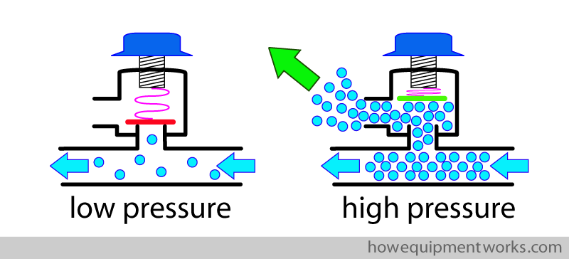
It would not be very pleasant to have reservoir bags bursting every few minutes, so we need a solution. The answer is to add an “pressure limiting outflow valve ” to the circle. This valve has a disc that is designed to open when a positive pressure develops on one side of it, thereby letting any excess gas to flow out and prevent further rises of pressure.
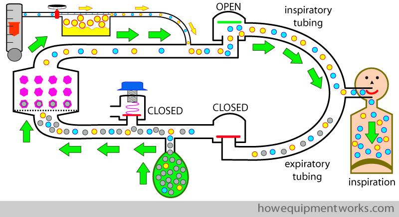
Now let us see how it works in the circle. The patient in our example is breathing spontaneously. During inspiration, the pressure in the system is low, so the pressure limiting outflow valve remains closed.
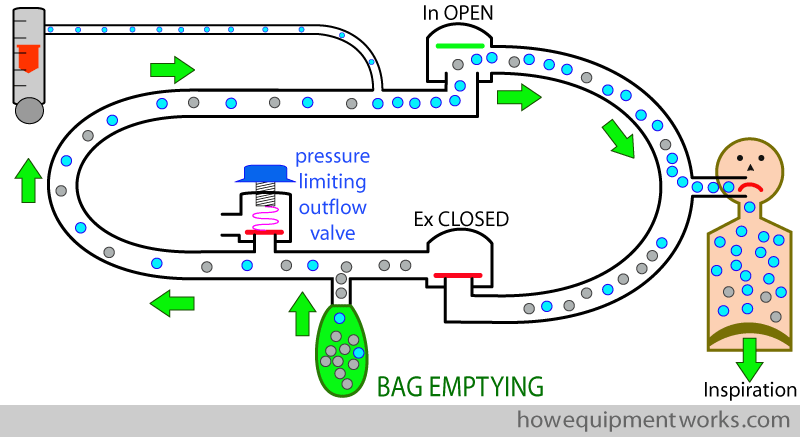
Now our patients breathes out. During early expiration, the expired gases go into the reservoir bag. Because the pressure is low, the pressure limiting outflow valve remains closed.
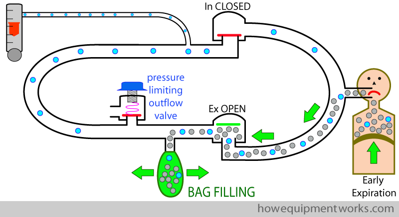
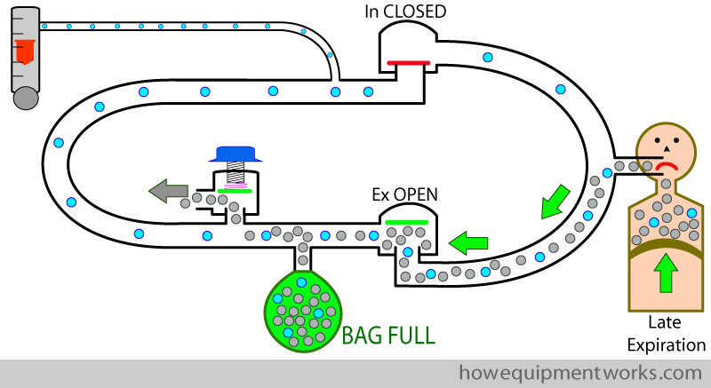
The expiratory gases fill the reservoir bag till it is fully distended. Once the bag is fully distended, the expired gases have nowhere to go and the pressure in the circle system rises. The rise in pressure causes the pressure limiting outflow valve to open, releasing the excess gases (grey arrow ) out of the circle system. In this way, the pressure limiting outflow valve lets excess gas escape and prevents a rise in the circle system pressure.
Carbon dioxide absorber
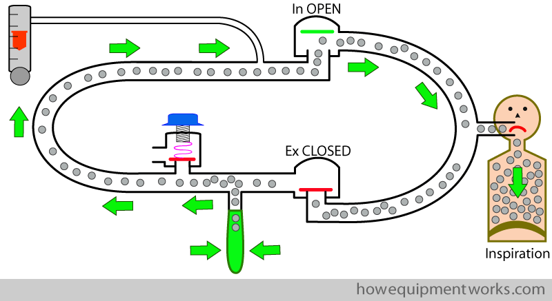
Now that our patient can inspire and expire nicely, we can ask the question; “Is he happy ? ” The answer unfortunately is “No “. The reason the patient is not happy is that, as I will explain soon, he is inspiring his own carbon dioxide ( shown as grey dots ).
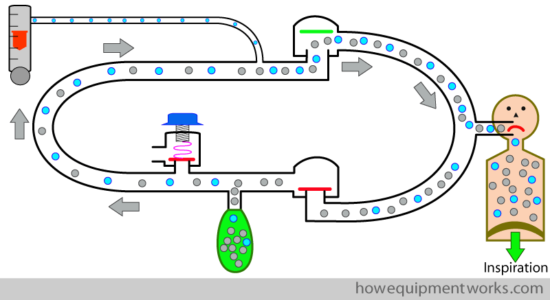
During expiration, most of the carbon dioxide goes into the reservoir bag, and once the bag is full, some of it goes out of the pressure limiting outflow valve.
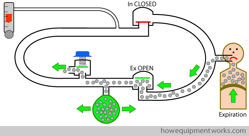
During the next inspiration, the patient breathes the carbon dioxide from the reservoir bag back into his lungs. If this situation is allowed to carry on, the carbon dioxide levels will keep on rising to dangerous, and even fatal, levels.
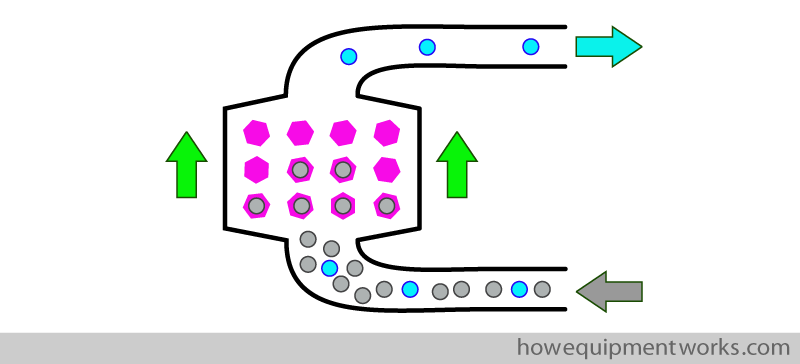
The solution is to use a device called a “carbon dioxide absorber ” which does, what its name says ! This device is simply a container, inside of which, there are chemicals (shown in pink below) that combine with any carbon dioxide ( shown as grey dots) that passes through it. While not strictly correct in chemistry terms, one can think of it as device that “absorbs ” any CO2 that passes through it ,and for this reason, the device is called a “CO2 absorber “. We will discuss finer details of this device later. For now, just remember that it absorbs CO2.
Let us include a CO2 absorber into our circle system. Now as the patient inspires, the CO2 containing gas from the reservoir bag passes through the CO2 absorber. The absorber “absorbs” the CO2, making the inspired gas CO2 free.
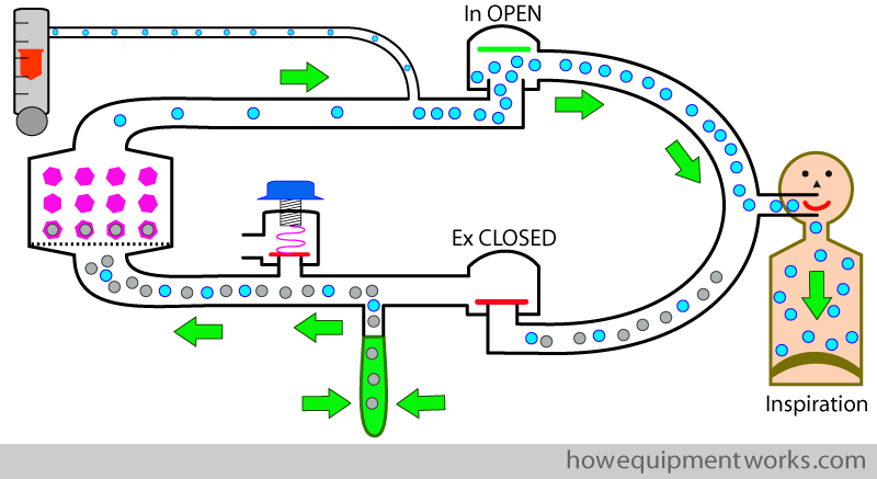
At least now you expect our patient to be happy, but when you look, he appears to be a little terrified instead ! The reason is that he is wide awake.
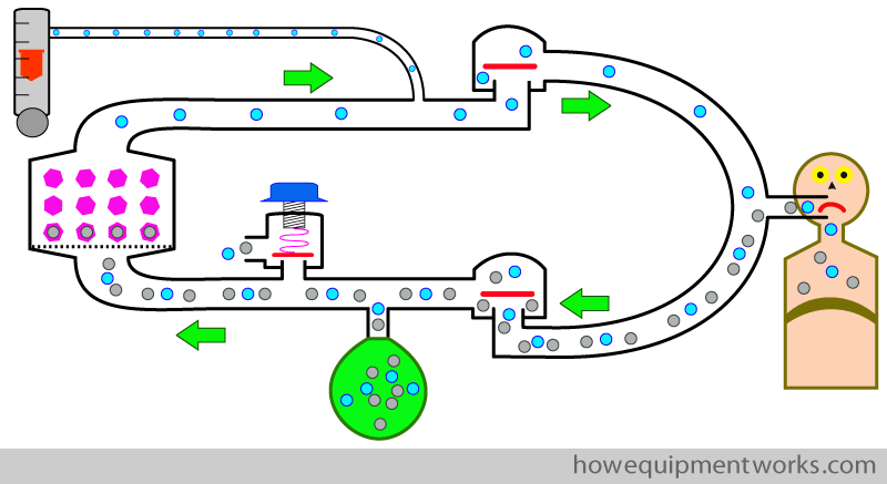
You need to give the patient anaesthetic gases to keep him asleep. We do this by adding anaesthetic vapours ( yellow dots ) to the fresh gas flow using a vaporiser.
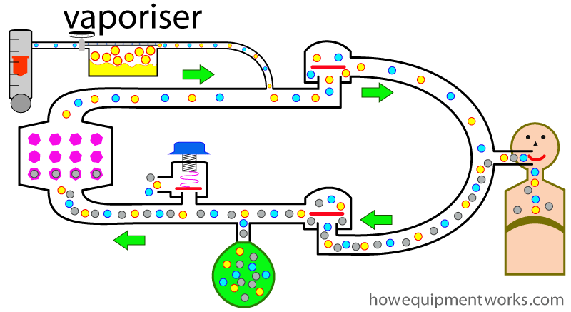
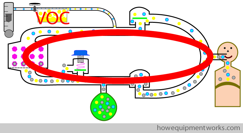
Unlike most components of the circle system such as the one way valves or the CO2 absorber, the vaporiser is placed “outside “ circle system. Using the vaporiser from the “outside ” in this way is called “vaporiser outside circle ” arrangement or “VOC “.
It is also possible to provide anaesthetic agent to the patient by placing the vaporiser ” inside ” the circle system as shown below. This arrangement is therefore called “vaporiser inside circle ” arrangement or “VIC “. The use of the vaporiser in this way is complicated ( and potentially dangerous) and is very rarely used. I have never used or seen it being used this way, so let me know if you know anyone who does. The design and use of vaporisers inside and outside a circle system is very different.
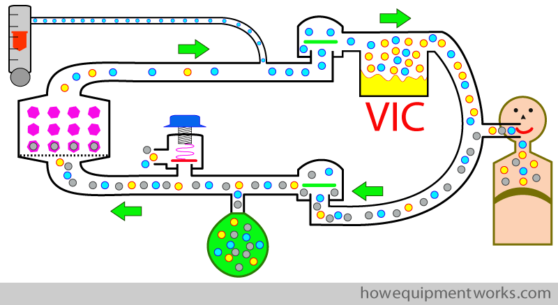
Since using the vaporiser inside the circle is very rare, I will not discuss it further. Instead, we will stick to the arrangement that is most commonly used, which is the “vaporiser outside circle” (VOC) arrangement.

Basic respiratory cycle in the circle system
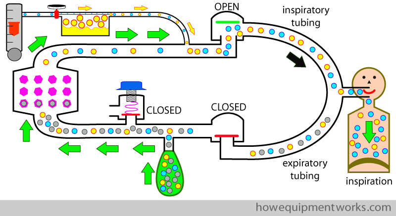
Now we finally have a complete circle system and an happy patient. Let us briefly recall how the circle system deals with one patient breath ( i.e. one inspiration and one expiration) in a spontaneously breathing patient (please note that now I am now describing spontaneous respiration. I will discuss positive pressure pressure ventilation later). We start with the image below, where we are adding fresh gas flow ( yellow arrows; which contains oxygen and anaesthetic vapor) into the circle system. When the patient starts to inspire, the expiratory one way valve closes and the inspiratory one way valve opens, making the patient inspire from the inspiratory tubing. The inspiratory gases consists of the fresh gas flow ( yellow arrows) plus the gases from the reservoir bag (green arrows), which because it has gone through the absorber, is CO2 free. During inspiration, the pressure inside the circle system is low and therefore the pressure limiting outflow valve ( valve with blue knob in diagram) remains closed.
During expiration, the patient expires the following : 1. CO2 he produced 2. anaesthetic gases he did not use 3. oxygen he did not use. I will divide the expiration into two periods : early expiration and late expiration. Let us start with early expiration. In this period, the expiratory gases go into the reservoir bag.
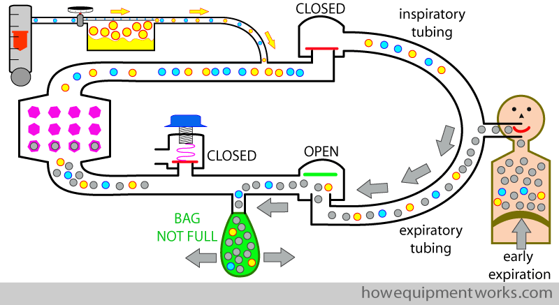
Once the reservoir bag is full, the expired gases have “nowhere to go” and the circle system pressure begins to rise. This opens the pressure limiting outflow valve that lets the excess gases out (which contains CO2, the anaesthetic agent the patient “did not use”, and the oxygen the patient “did not use” ). The anaesthetic agent that goes out of the pressure limiting out flow valve is lost out of the circle system permanently and is considered to be “wasted”.
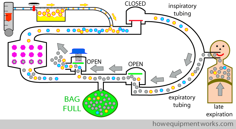
Now the cycle repeats and the patient inspires from the reservoir bag, reusing the anaesthetic agent in the bag.
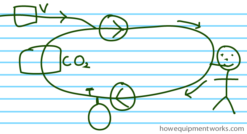
By the way, as you have seen, the diagrams I have drawn are somewhat colorful. Of course, when you revise or need to draw the circle system in an exam, you might want to do a simpler version ( perhaps something a little better than what I have drawn here !).
A small break for you !
Let us take a small break now. Here are two “circle” related optical illusions for you to enjoy.
The “Red Circle” illusion
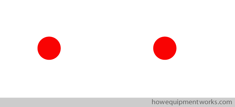
In the diagram below, which red circle is bigger, the one on the left or the one on the right ?
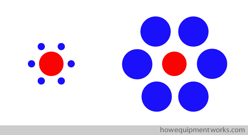
In reality, they both are exactly the same size ! You can measure the two red circles shown above if you do not believe me.
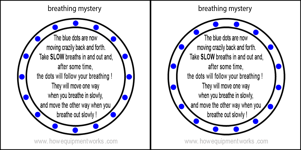
“Mystery Breathing Dots”
Here is an optical illusion that I invented. You need to try it in a relatively quiet environment. Please let me know if it worked for you by clicking the feedback button in the menu on top of this page.

Everyone wants happiness. However, according to psychologists, many of us think in certain ways which can prevent us from being happy. One may not even realise that one is thinking in such ways. The free website at the link below explains the concept of “Happy Thinking” which is about thinking in ways that help one to be happy. Once you discover “Happy Thinking” you will find yourself becoming a happier person. The website is completely free.

Positive pressure ventilation:
So far we have discussed how the circle system works in a patient breathing spontaneously. Let us now discuss how the circle system works when the patient is ventilated using positive pressure. While the basic concepts remain the same for both, spontaneous and positive pressure ventilation, there are also some differences.

The circle system behaves some what differently, depending on if you use your hand and reservoir bag to ventilate the patient, or if you use a mechanical ventilator to ventilate the patient.
Positive pressure ventilation using reservoir bag :
I will first discuss ventilation using a reservoir bag and your hand. Let us now try and give the patient some positive pressure breaths by squeezing the bag. I am no artist, so will indicate squeezing the reservoir bag using a symbol of a hand.
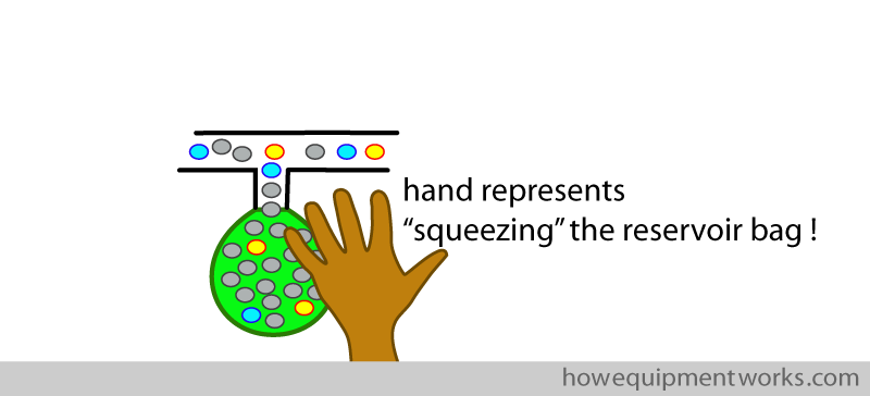
You will see in the diagram below, that squeezing the bag doesn’t seem to ventilate the patient ! This is because the positive pressure created by squeezing the bag opens the pressure limiting outflow valve, letting the gas flow out (red arrow) instead of going into the patient.
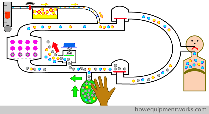
At this point, I need to make a small confession. I didn’t tell you the full story about what I have, so far in our discussions, called the “pressure limiting outflow valve”.
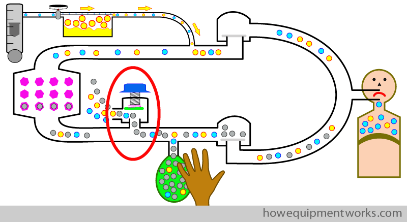
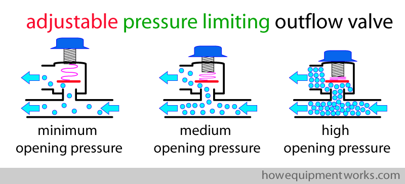
As mentioned before, I have been calling the valve a “pressure limiting outflow valve”. What I did not tell you before is that this valve is actually “adjustable” by you. i.e. it allows you to “adjust” the pressure at which the valve opens. I will next explain how it does this, as you need to know more about this valve to understand positive pressure ventilation using the reservoir bag. Since the valve is adjustable, we should call it “adjustable pressure limiting outflow valve” ( APL outflow valve).
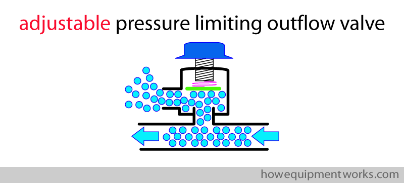
The valve has a spring which I have shown shown in pink below.
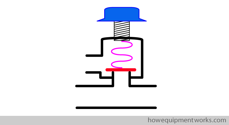
The spring applies a force onto the disc.
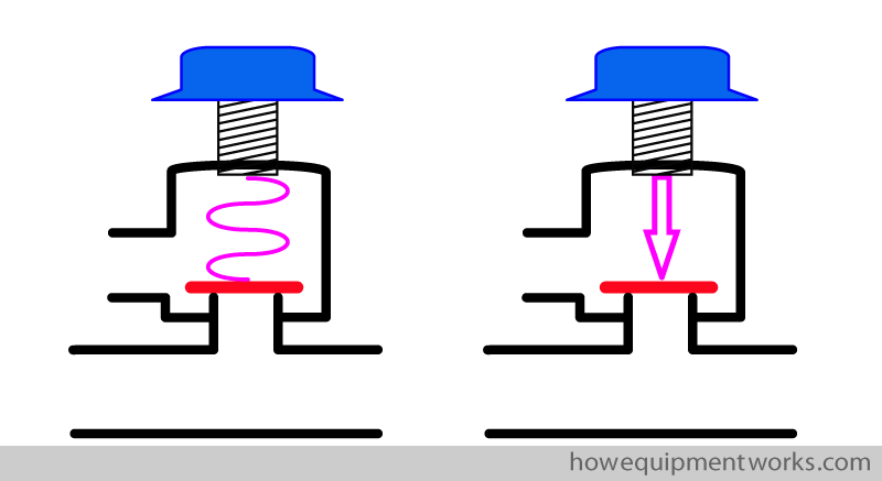
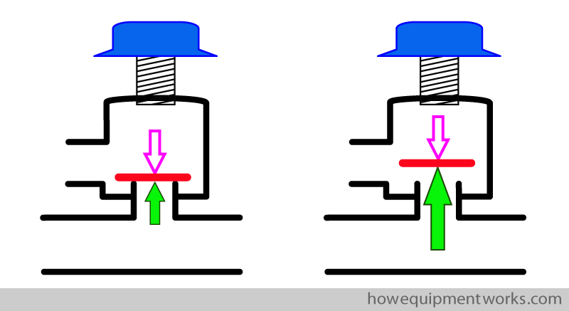
The valve will open only when the pressure inside the circle system generates a force ( shown as green arrow ) high enough to overcome the force applied by the spring ( pink arrow ).
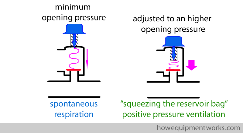
You can adjust the pressure applied onto the disc by turning the knob of the adjustable pressure limiting outflow valve. When you want the valve to open even for a low pressure in the circle system, the spring is kept at a very relaxed state. If you want the valve to open at higher pressures, you turn the knob to make the spring more compressed. This increases the force the spring applies onto the disc.
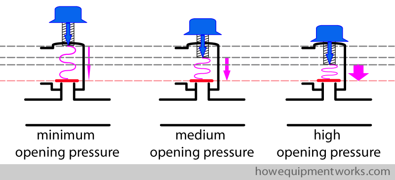
In this way, you can adjust the circle system pressure at which the adjustable pressure limiting outflow valve (APL outflow valve) will open.
Normally for spontaneous respiration, this valve is set to open at a minimal pressures (i.e. only a slight pressure in the circle system will make the valve open). When you use the reservoir bag to provide positive pressure ventilation, you need to adjust the APL outflow valve to open at a higher pressure. Do not worry, I will explain this to you in more detail later.
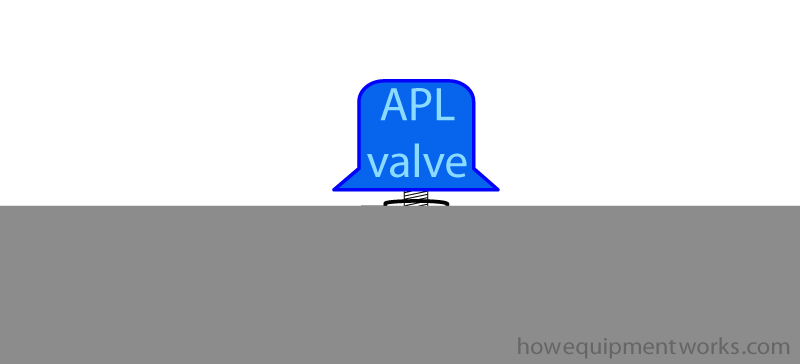
Unfortunately ( or fortunately ?) most modern anaesthesia equipment tends to keep “ugly” tubes etc hidden. So in your anaesthetic machine, the adjustable pressure limiting out flow valve may look only like this !
By the way, the outflow of gases from the APL outflow valve is often connected to a scavenging system, so that the gases are safely sent to the outside of the hospital.
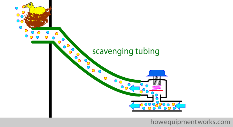
Scavenging systems are an important topic which I cannot discuss further here . Let me know, through the “contacts” page of this website, if you want me to add a section on scavenging systems.
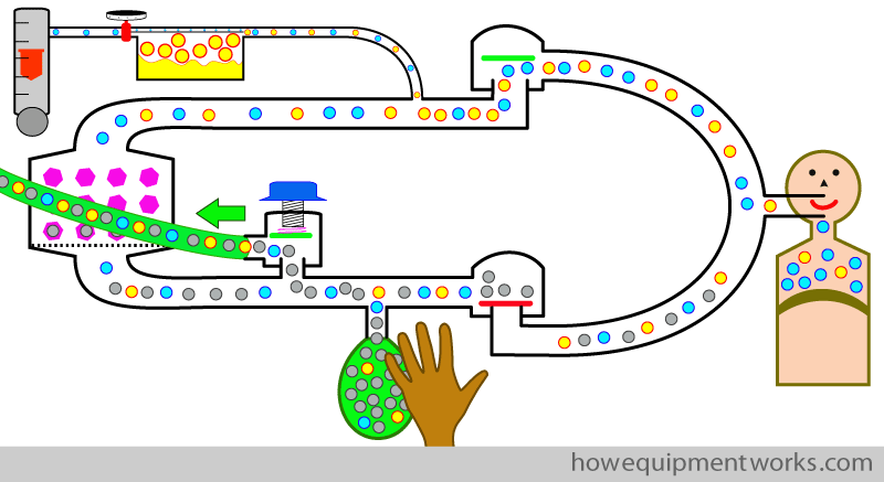
Now let us return to the circle system, where we are trying to use a reservoir bag and your hand to give positive pressure ventilation. Below is the circle system as it was used in our previous discussion on how it works with spontaneous respiration. As mentioned before, when using the circle system with spontaneous respiration , the APL outflow valve is set to minimum (i.e. it opens at a very low pressure).
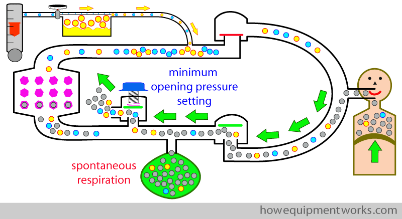
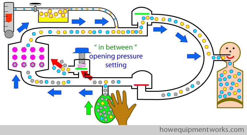
Now with this setting ( minimum opening pressure setting ), if you try to give a positive pressure breath to the patient by squeezing the reservoir bag, the gases go out of the APL outflow valve, and the patient does not get ventilated.
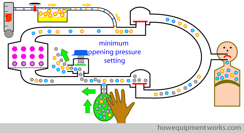
Let us try again. This time we set the APL outflow valve to its maximum opening pressure (i.e. it will open only when a very high pressure develops inside the circle system). Now, you will find that we can give positive pressure breaths as nothing goes out of the APL outflow valve.
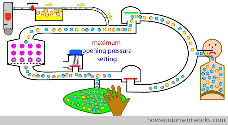
Oh! oh! There is a problem ! You will remember from our previous discussion on circle system basics, that excess anaesthetic gases need to come out of the APL outflow valve. However, in our example, we have adjusted the APL outflow valve to the maximum opening pressure. In this setting, the excess anaesthetic gases can’t flow out of the APL, and instead, it collects in the reservoir bag, distending it to dangerous levels ! So, in the maximum opening pressure setting, you may be able to give a few breaths, but soon the circle system pressures will rise to a dangerous level.
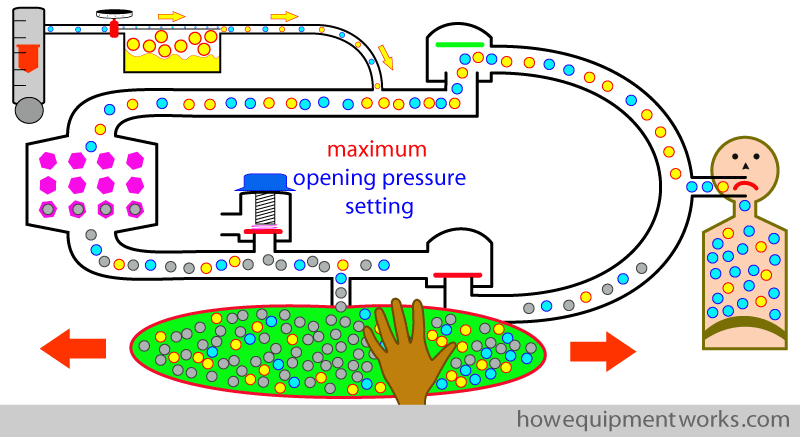
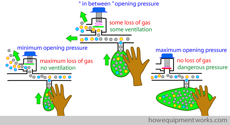
The answer is to set the APL outflow to a pressure that I would like to call the “in between pressure”. This is an APL opening pressure you choose that is somewhere in between being too low ( causing excessive gas loss) and being too high ( causing over distention of reservoir bag and dangerously high pressure).
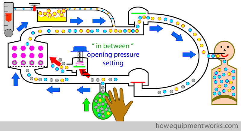
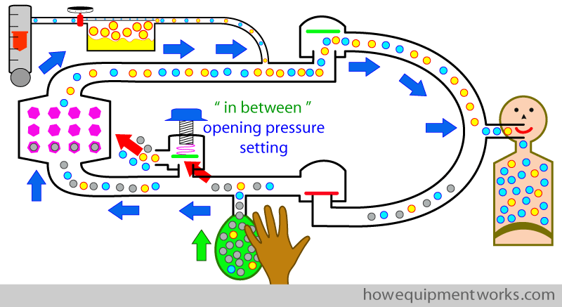
With the APL outflow valve is set appropriately somewhere in between minimum and maximum, part of the anaesthetic gases from the reservoir bag goes to the patient ( blue arrows) while at the same time, another part of the anaesthetic gases go through the APL outflow valve ( red arrows).
The gases that flow out of the APL out flow valve during the positive pressure inspiration is wasted ( red arrow). Therefore, to compensate, one may have to increase the fresh gas flow ( yellow arrow) to compensate for this loss.
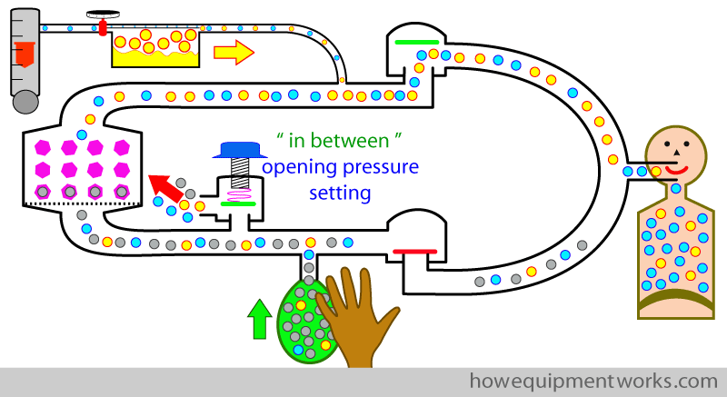
During expiration, the expired gases go into the reservoir bag.
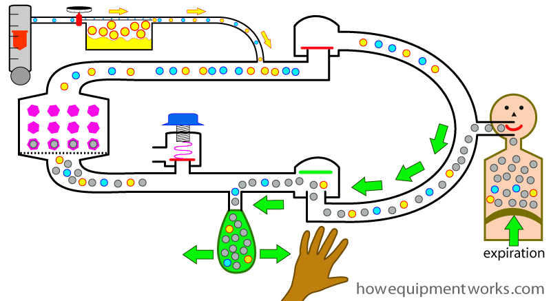
The circle system works slightly differently depending on whether you give positive pressure ventilation by squeezing the reservoir bag ( as we discussed before) or by using a mechanical ventilator. We will now put our hands away and discuss how mechanical ventilation works in the circle system.
Positive pressure ventilation using ventilator :
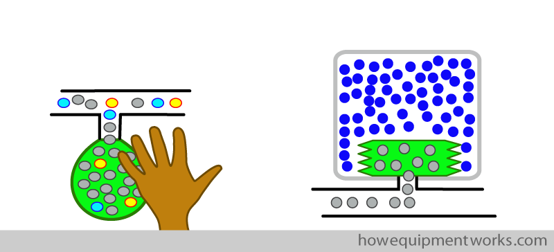
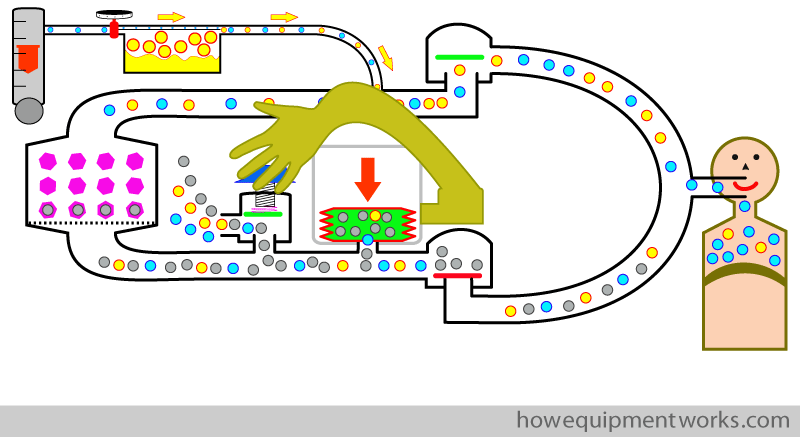
I will not discuss ventilators in great detail here as it is an extensive topic on its own. One example of ventilator design is the so called “bag squeezer ventilator “. Basically, as the name implies, this type of ventilator “squeezes” the bag. However, this ventilator doesn’t have hands like you and me, so it uses a clever design to replace our hands. The bag is placed inside a sealed “container ” shown as a grey outline below. In practice, the “container” is usually transparent so that you can see what is going on.
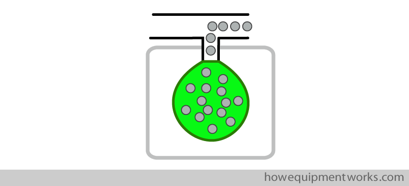
In this ventilator design, the “container and bag” is placed “up side down”.
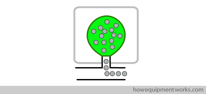
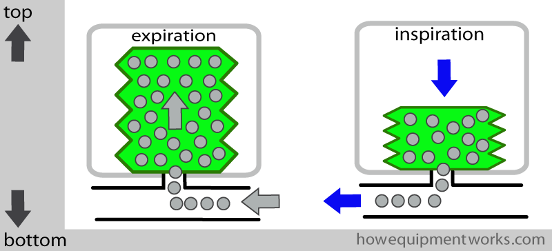
The “bag” in these ventilators is present in the form of collapsible bellows. During expiration, the gases in the patient’s lungs empty into the bellows, making the bellows rise upwards. For inspiration, as I will soon explain, the ventilator “squeezes” the bellows downwards, pushing the gases towards the patient.
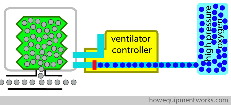
The ventilator “container” is connected to a ventilator controller. The controller is in turn connected to an high pressure source of oxygen. As I will explain soon, this oxygen at high pressure ( blue dots) will be used to “squeeze” the bellows.
Let us first talk about inspiration. It begins with the ventilator controller letting oxygen at high pressure enter into the container.
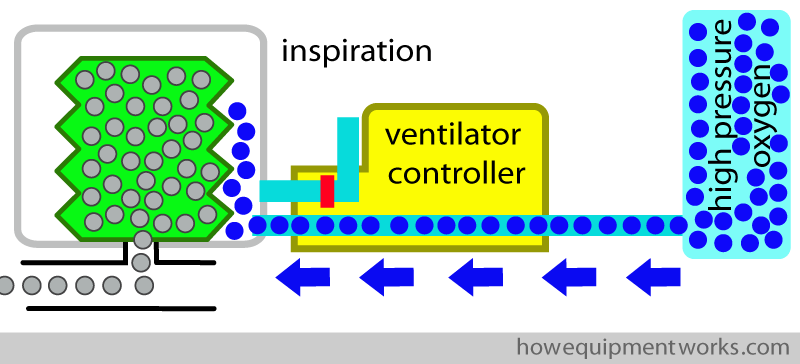
The oxygen at high pressure pushes down (“squeezes”) the bellows, pushing the anaesthetic gases into the patient. The high pressure oxygen is often called “the driving gas”.
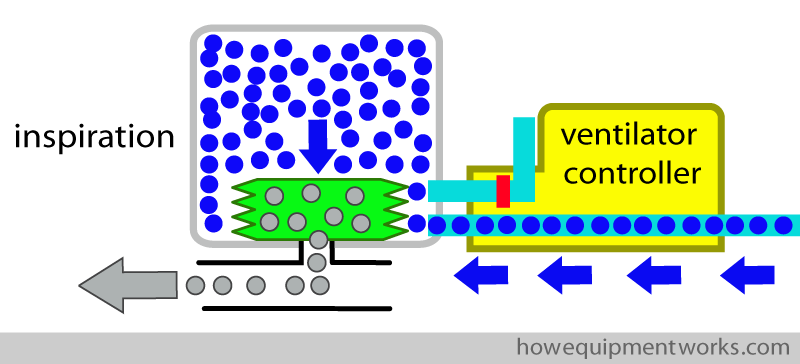
For expiration, the ventilator controller stops the flow of pressurised oxygen into the container. During expiration, the gases in the patient’s lungs empty into the bellows, making the bellows rise up. The rising bellows pushes out the “used up” driving gas (oxygen) through ventilator controller into the atmosphere.
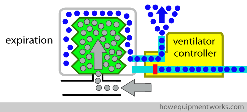
It is important to note that the pressurised oxygen ( blue dots) used to squeeze the bellows does not go into the patient. Similarly, the patient gases ( grey dots) do not go into the container.
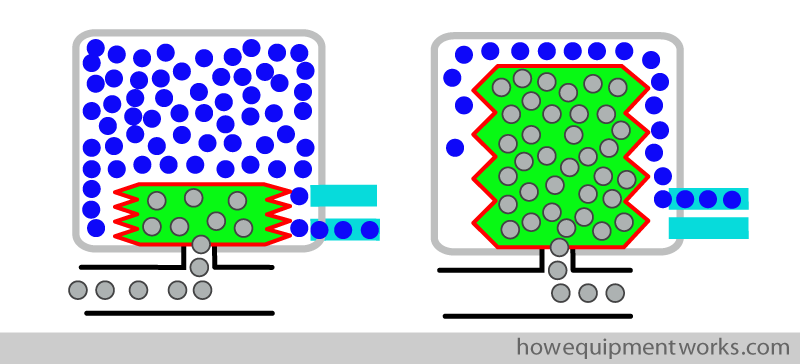
In other words, the oxygen used to squeeze the bellows (driving gas) is thrown away after each breath.
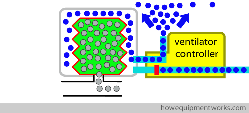
Some people imagine that this design is like placing the reservoir bag in a “transparent bottle “. For this reason, this design is often called a “bag in the bottle ” ventilator (you do have to exercise your imagination a bit to see that the bellows looks like a bag and that the transparent container looks like a bottle).
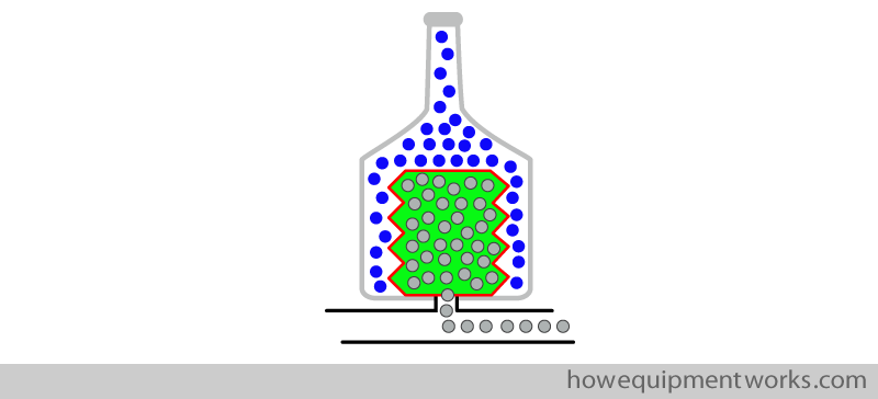
Now let us connect our ventilator to the patient and see what happens. At the moment, the APL valve is set at the minimum opening pressure and you notice that the patient is not get ventilated ! This is because, during the positive pressure inspiration, the gases are flowing out of the APL outflow valve and not going to the patient.
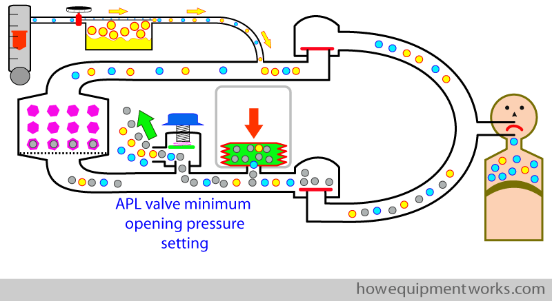
During positive pressure ventilation using a mechanical ventilator, the APL outflow valve is used in a different way to how it is used during spontaneous respiration. To discuss this, I need to briefly go back to talking about hand ventilation using a reservoir bag.
You will remember that when we talked about hand ventilation using the reservoir bag, that one can set the APL outflow valve to an “in between setting”. In this setting , you will also recall that while there is some ventilation, there is also wastage of some gas ( red arrow).
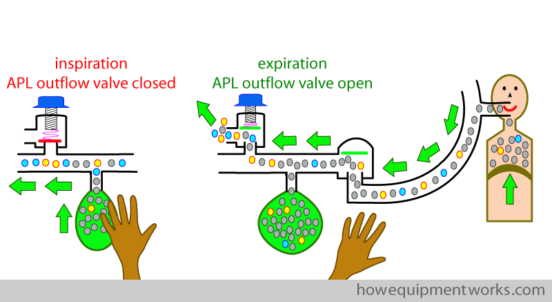
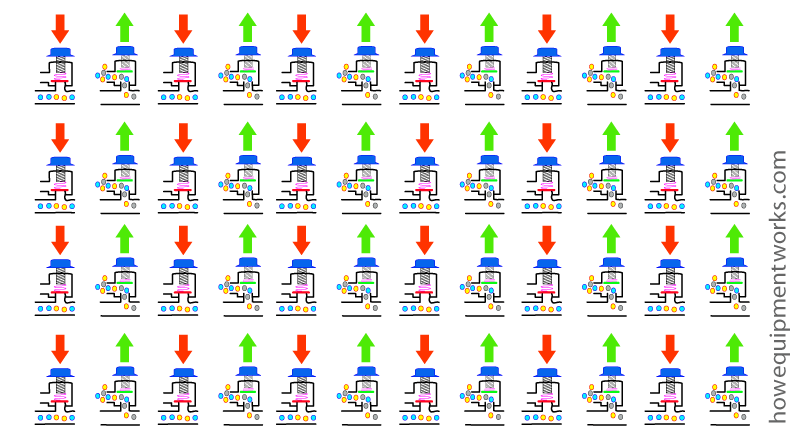
However, at the time of discussing hand ventilation, I did not mention another method of adjusting the APL outflow valve. This alternate method is different to the “in between APL outflow valve setting” method discussed so far. I will explain this alternate method of adjusting the APL outflow valve during hand ventilation now, because it has something to do with how the APL outflow valve is used when using a mechanical ventilator. I would like to name this alternate method as the “rapid open close method”. In the “rapid open close method”, when giving a positive pressure inspiratory breath by squeezing the reservoir bag, one fully closes the APL outflow valve. Since the valve is closed (i.e. maximum opening pressure) , there is no loss of anaesthetic gases.
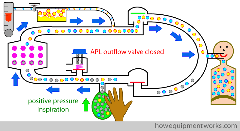
Then in expiration, one fully opens the APL outflow valve (i.e. minimum opening pressure). Most of the expiratory gas will go into the reservoir bag, where it will collect. Only once the bag is full, will the excess gases go out of the APL outflow valve.
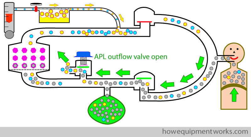
For the next positive pressure inspiration, the APL outflow valve is again closed and the bag is squeezed. Since the APL outflow valve is closed, no gases leak out during the positive pressure inspiration.
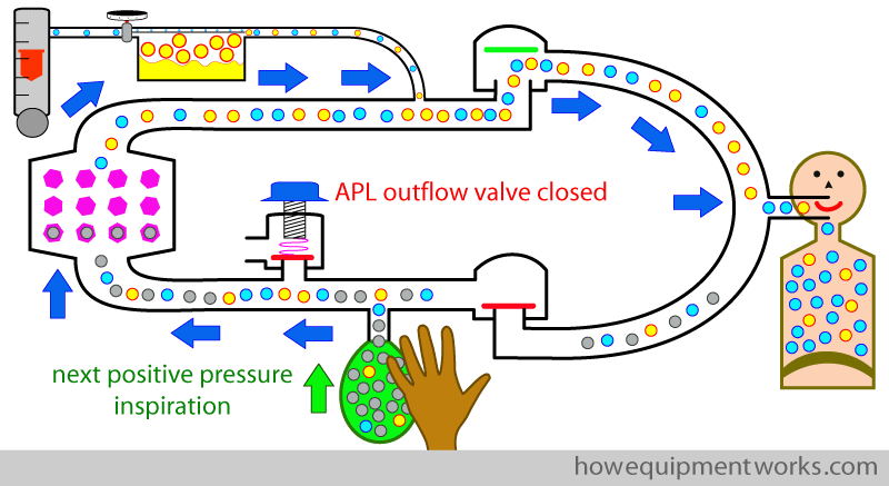
This “rapid open close” method is quite economical as no gas is lost during inspiration, and during expiration, the bag is filled before the excess gases are thrown out of the APL out flow valve.
You may now ask, if this “rapid open close” method is less wasteful, why didn’t I mention it before ? The reason is that, to use the “rapid open close” method, you would have to open and close the APL outflow valve for each breath ! Imagine that you decided to use the “rapid open close” method to hand ventilate a patient for one hour, at a rate of ten breaths per minute. That means that you would have to open and close the valve 600 times in that hour ! So the “rapid open close method” is a theoretical method. Please do not do it in practice !
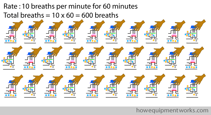
So, to prevent breaking your hand and breaking the APL outflow valve, better to stick to the “in between setting” method !
Now let us return to the mechanical ventilator. Unlike us delicate humans, it is capable of working tirelessly ! The ventilator can rapidly open and close an APL outflow valve many thousands of times a day with no complaints.
Since the ventilator can do things tirelessly, it would make sense for it to use the “rapid open close method”, as this method wastes less anaesthetic gases through the APL outflow valve. In practice, the ventilator of course doesn’t use some kind of mechanical “hand ” that turns the APL outflow valve ( though that would have looked great) .
In practice, the ventilator has its own APL outflow valve that it can control. We will call this the “ventilator outflow valve”.
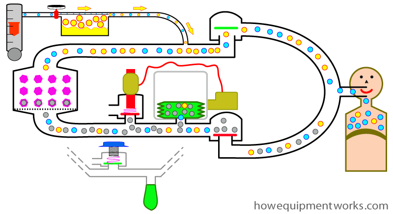
During inspiration the ventilator closes the “ventilator outflow valve” and “squeezes” its bellows in the manner described earlier. No gases go out of the ventilator outflow valve during inspiration.
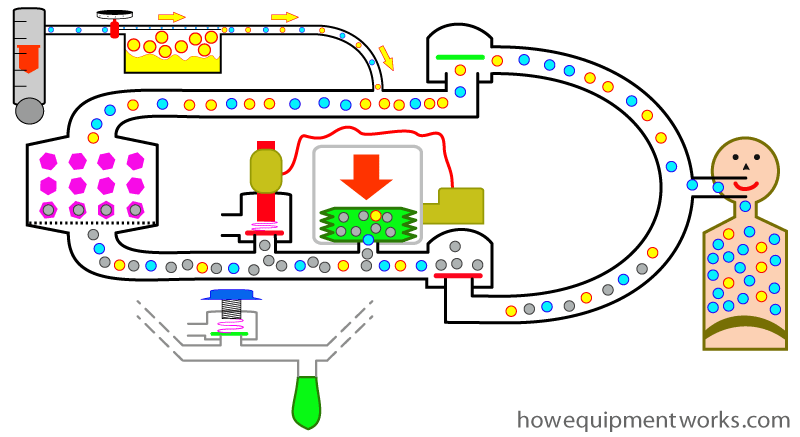
During expiration, the ventilator sets the ventilator outflow valve to a minimal pressure setting. The expiratory gases first fill the bellows and any remaining excess gas goes out of the ventilator outflow valve.
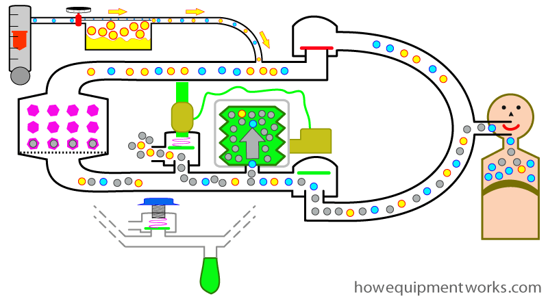
The cycle then repeats itself. The ventilator closes its ventilator outflow valve and gives the next inspiratory breath.

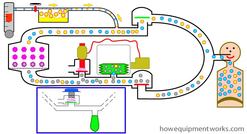
When the ventilator is in use, ” your APL outflow valve ” and ” your reservoir bag ” ( both shown inside blue box below) are not used. Therefore in many modern anaesthetic machines, when you select the ventilator, these are therefore automatically disconnected from the circle system.
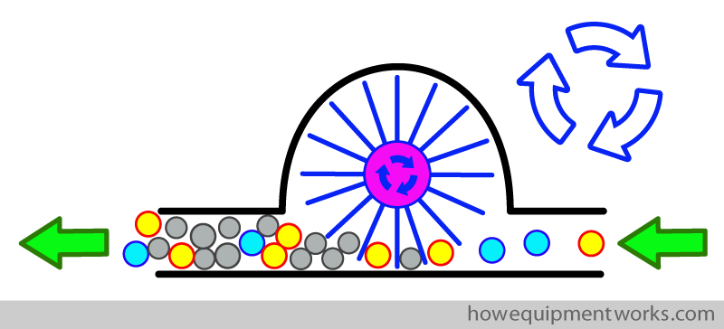
It is very important to keep in mind that I have discussed just one type of ventilator so that you can generally understand how things work. Your anaesthetic ventilator system may be completely different and for patient safety you must refer to appropriate documentation and understand its functioning before using it. Modern engineering makes it possible to have many different designs. For an example, one design of a ventilator uses a fan (turbine) that spins extremely fast and pushes the anaesthetic gases forwards during inspiration (i.e. it doesn’t have any bellows).
Main advantages of the circle system
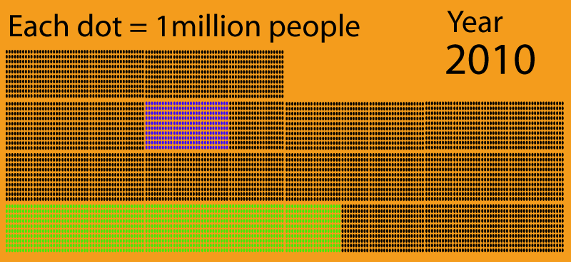
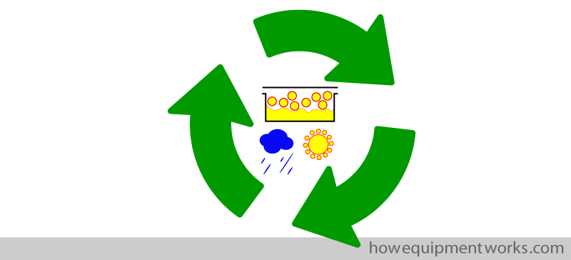
As you have seen, the circle system is a little complicated. So the next question is, “Why do we use it ? “ The reason has got to do with “recycling”. Recycling is something we are all (hopefully) familiar with as the natural resources in the world are running out fast. The main problem I suppose is that the human population is growing very quickly and we all are consuming a lot of resources. I was quite surprised to learn that, less than a hundred years ago, the population on Earth was only 1 billion.
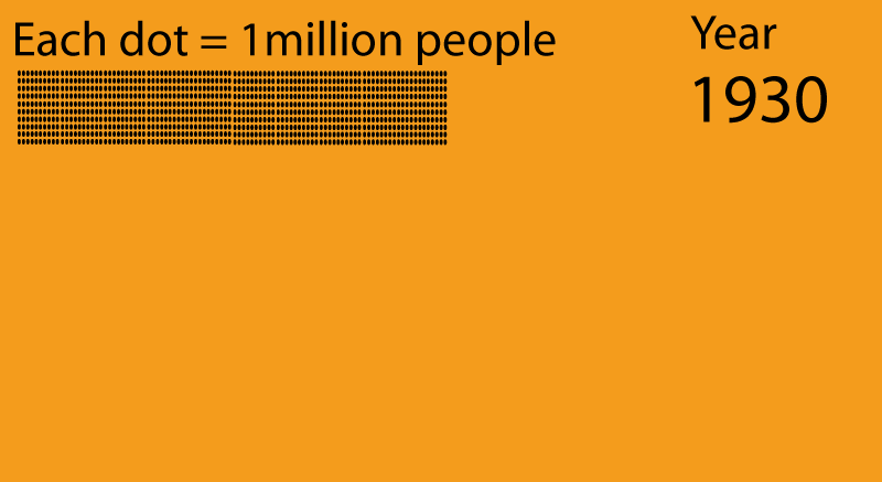
Only seventy years later, the population had risen to 7 billion ! We continue to multiply fast and the population is expected to rise to 9 billion by the year 2040. To help you appreciate the numbers, I have coloured the population of India as green dots and the population of the USA as blue dots. With so many people consuming the limited resources of the world, it is very important that we recycle whatever we can.
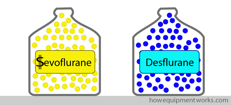
Let us return to the circle system ! Well, in anaesthesia, we also need to worry about recycling. Now you may ask, “What is so precious in anaesthesia that we need to recycle ? ” The answer is that some of the modern anaesthetic agents are quite expensive (e.g. Sevoflurane, Desflurane), so we would save significant amounts of money if we recycled them.
Apart from the cost, anaesthetic agents released into the atmosphere also contribute to global warming. Compared to other causes of global warming (e.g. cars), the effect caused by anaesthetic gases is tiny. Nevertheless, it still makes sense, whenever feasible, to recycle anaesthetic gases instead of letting them pollute the atmosphere.

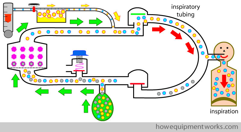
So how does the circle system come into the story of recycling ? Well, the big advantage of the circle system is that it recycles expensive anaesthetic gases. Let me explain how it does this. During inspiration, anaesthetic agent ( yellow dots ) goes into the patient.
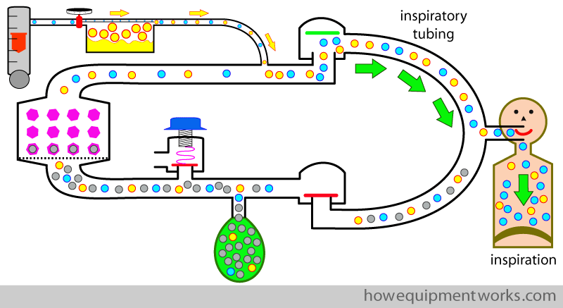
During early expiration, most of the anaesthetic agent that the patient has not taken up goes into the reservoir bag.
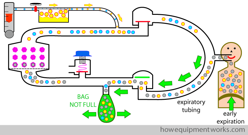
Once the bag is full, the remaining anaesthetic agent and other gases go out via the APL outflow valve. This bit of gases is lost forever and is therefore “wasted”.
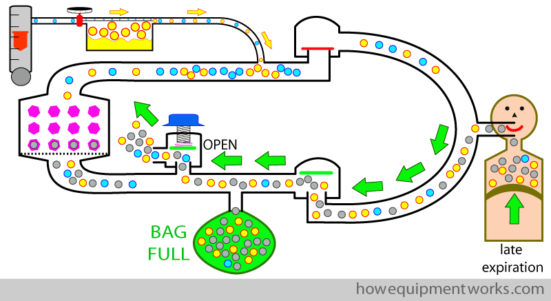
During the next inspiration, the patient inspires from reservoir bag. The gas from the reservoir bag contains anaesthetic agent that the patient expired in his previous expiration (green arrows) and this is added to the anaesthetic agent in the fresh gas flow ( yellow arrows). The combined mixture (red arrows) goes into the patient. The adding of the anaesthetic agent from the reservoir bag (i.e. “recycled anaesthetic agent”) reduces the amount of anaesthetic agent we need to give in the fresh gas flow, saving money and causing less pollution.
Along with anaesthetic agent, there are two more things that are worth recycling : moisture and heat. The fresh anaesthetic gases are dry and cold. Continuous exposure to dry gases can make the respiratory tract dry leading to complications. Anaesthesia is also associated with heat loss, so any conservation of heat will be beneficial. The circle system helps to conserve both, moisture and, to a lesser extent, heat, by recycling them in a similar way to how the anaesthetic gases are recycled.
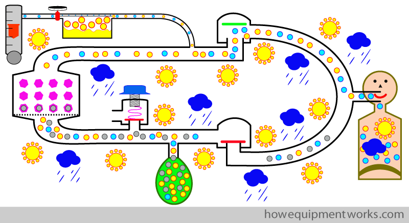
So, in summary, the circle system is great because it conserves (recycles) anaesthetic agent, moisture and some heat.
How does a circle system look ?
The diagrams that I have drawn so far are “typical ” diagrams of a circle system. However, it is important to know that the individual parts can be arranged differently. For an example, it is possible to attach the reservoir bag before or after the CO2 absorber as shown below.The chosen location of the bag will make the system operate slightly differently.
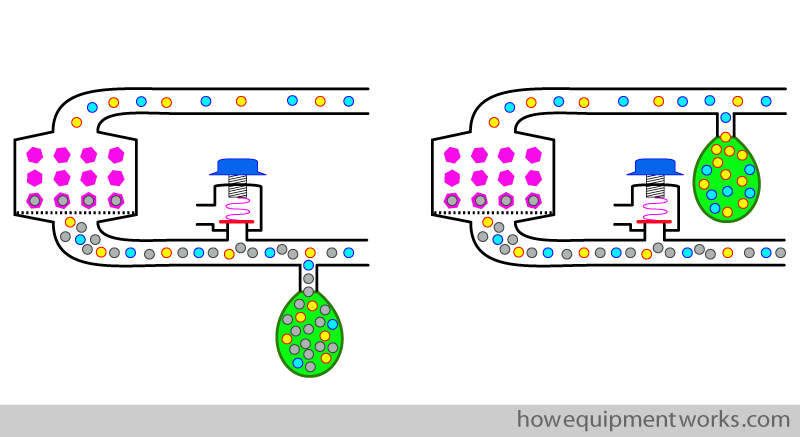
The other parts can also be arranged in a variety of ways. For further details regarding the arrangement of the individual parts of the circle system in your anaesthetic machine please refer to the instruction manual. However, my personal opinion is that at this stage, to understand the basic concepts, just stick to one diagram.
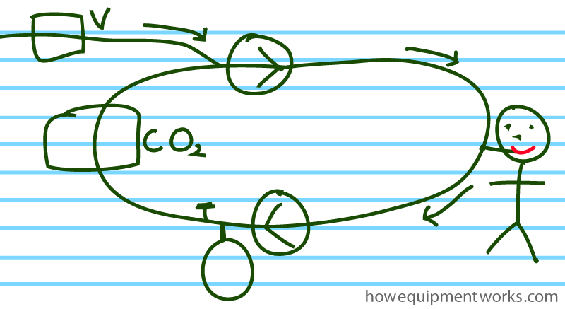
Also, I have so far drawn the circle system to look more or less like a circle !
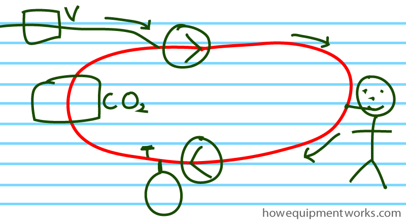
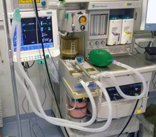
However, it is important to understand that I drew it as a “circle ” only to help you to understand the concepts. In reality, you are not going to see a perfect circle coming out of your anaesthetic machine ! The actual “circle ” will be quite distorted, the parts arranged in a manner that is practical. Modern anaesthetic machines tend to hide a lot of the tubing, so you will have to refer to the instruction manual to work out the gas flow path inside the machine.
A little more detail of some of the parts:
To avoid confusion, in our previous discussions, I left out some details about some of the parts of the circle system. Let us discuss them now.
One way valves:
As discussed at the beginning, the circle system needs two one way valves.
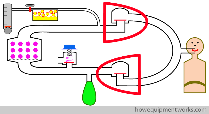
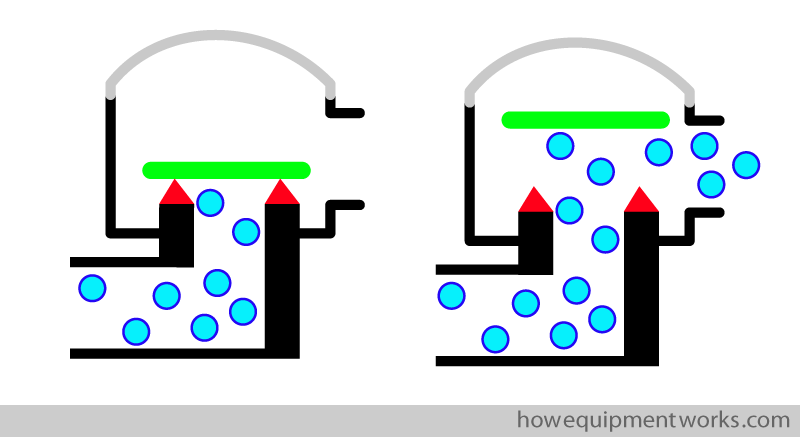
The one way valves are specially designed to work reliably. A typical design will consist of a disc that sits over an opening. The disc opens one wa , letting the gas through in that direction, but shuts the other way, preventing the gases from going the other way. The top of the valve enclosure is usually transparent so that you can observe the disc moving and confirm that it is working properly. The valve will usually have a “arrow ” marking, showing the direction of flow it allows.
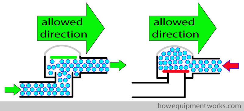
The correct functioning of these one way valves is important for the correct functioning of the circle system. For an example, if the expiratory one way valve fails and gets stuck in the open position, the patient may just breath in and out from the expiratory side of the circle and not get much oxygen.
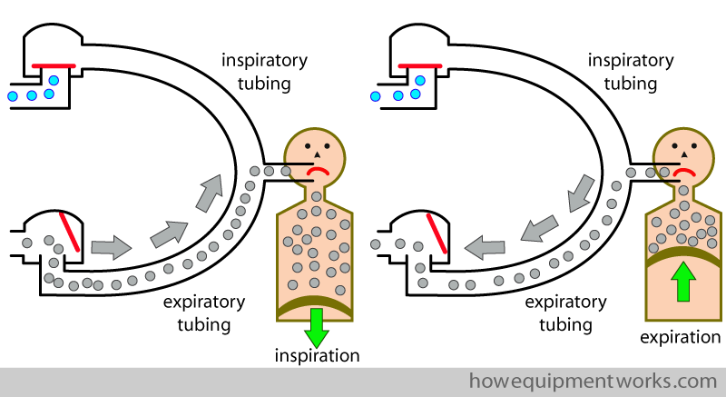
If the disc of the valve “sticks ” to its supports ( red squares in diagram) , there will be obstruction to flow.
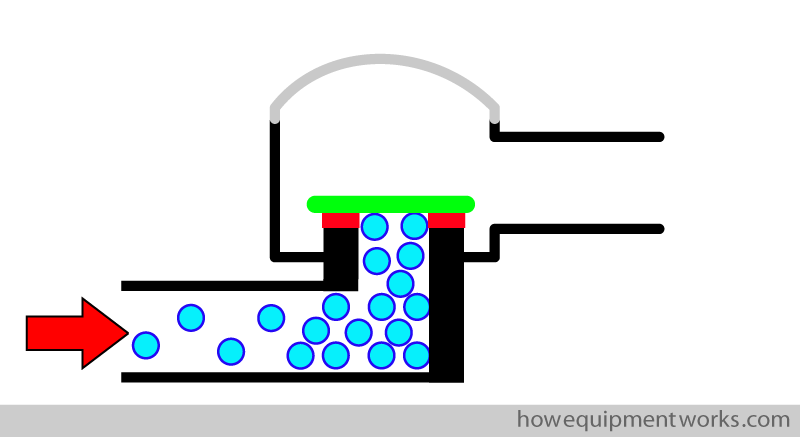
To minimise this happening, the disc is usually made to sit on “sharp” supports ( red triangles in diagram) to reduce the area of contact between the disc and its supports. The reduced surface area of contact reduces the area that can “stick to each other” and the valve therefore opens easily.
Carbon dioxide absorber:
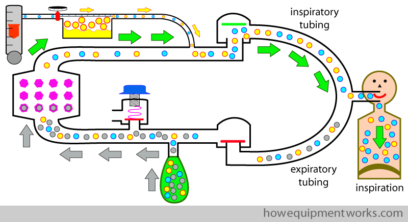
A key component of the circle system is the carbon dioxide absorber ( CO2) . As you have seen, in the circle system, the patient inspires his own previously expired gas from the reservoir bag ( grey arrows). This expired gas has CO2 which needs to be removed. This is done by a container called a “CO2 absorber ” inside of which are chemicals that combine with the CO2 and remove it from the gas mixture.
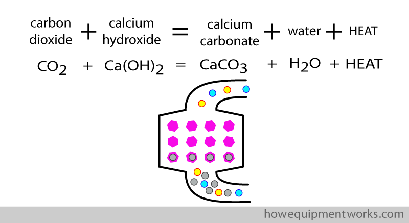
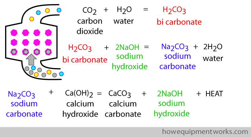
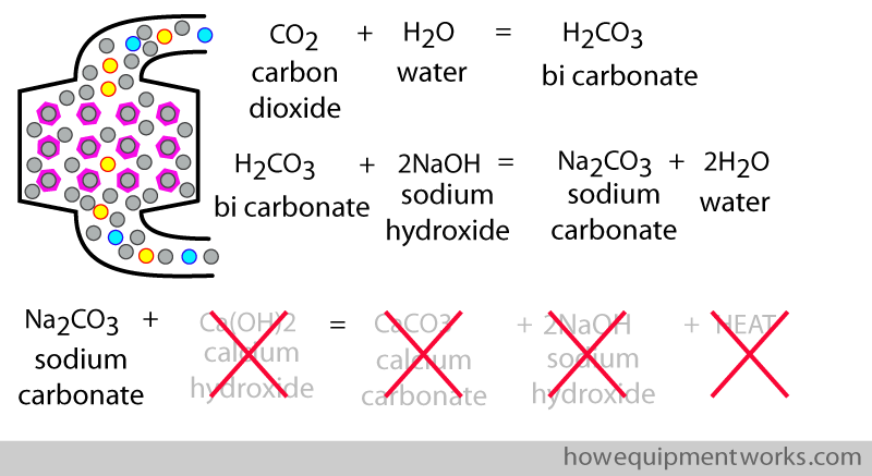
The CO2 is removed by chemical reactions. My chemistry knowledge is minimal, so I am sorry I cannot give you much details. The main chemical that is often used to absorb CO2 is calcium hydroxide. The basic equation is given below. This reaction also produces water and heat.
The above reaction can be quite “slow”, so a small quantity of sodium hydroxide ( NaOH) may be added to speed things up. Below is a more complete set of equations describing what happens inside the carbon dioxide “absorbing” container. The equations start with the patients carbon dioxide reacting with water that is present in the mixture of chemicals.
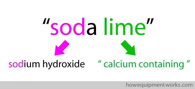
When a CO2 absorber contains sodium (e.g.like the sodium hydroxide in the above equations), it may be called “soda lime “. “Lime” is a word used to describe calcium containing material.
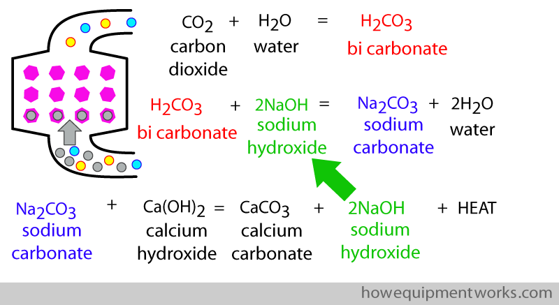
Note that in the equations, the sodium hydroxide is re used ( “recycled” ). Therefore the CO2 absorber does not need to contain much sodium hydroxide.
If all this is confusing, just try and remember that the CO2 ultimately becomes calcium carbonate plus water plus heat.
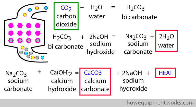
Once the calcium hydroxide is used up,the equations cannot “move forwards” and the absorber cannot combine with anymore CO2. One would say that the absorber is “exhausted ” and the chemicals in it will need to be replaced.
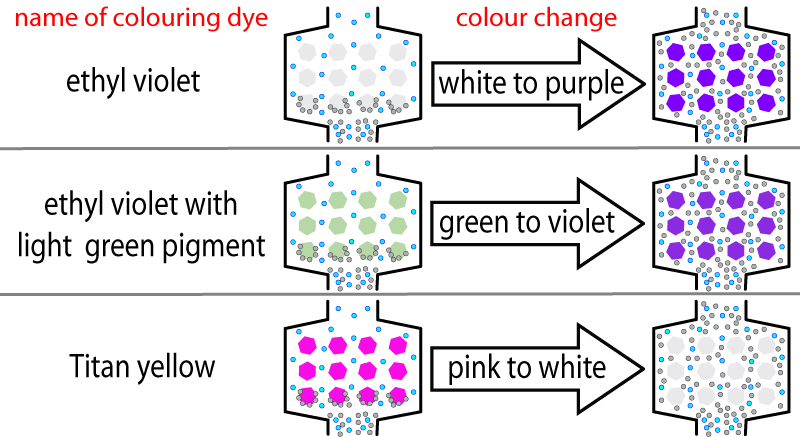
So how would you know when an absorber needs replacing ? When the absorber chemicals get used up, the pH decreases (i.e. it becomes acidic). The absorber has a colouring dye that is sensitive to the pH of the mixture. When the pH changes ( due to exhaustion), the dye changes colour telling you that it is time to change the absorber chemicals. There are different dyes available, so you must check to see which one is in use in your absorber and know what colour change will indicate absorber exhaustion. Below are some example of dyes used. The colours are only approximate, so the diagram below is not for clinical use.
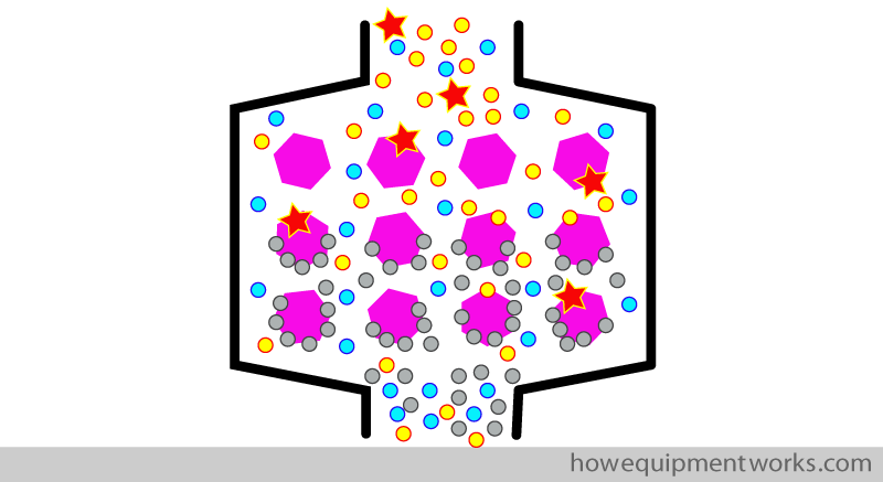
The chemicals that are to be used in absorbers are available in the form of granules ( small pieces). These granules are placed inside the absorber container. When the absorber chemicals are ” exhausted ” they are removed and replaced with fresh chemical granules. The anaesthetic gases and carbon dioxide pass between the spaces of the granules. As the gases come into contact with the granules, the chemicals in the granules combine with the carbon dioxide as shown in the equations shown before.
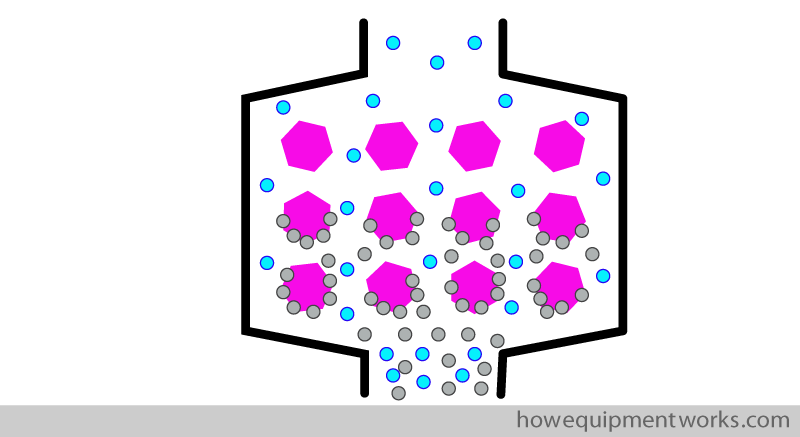
The granule size needs to be chosen carefully. If the granule size is too small, they will become more “tightly” packed and there will be inadequate space between the granules for the gases to pass, leading to an unacceptably high resistance to flow.
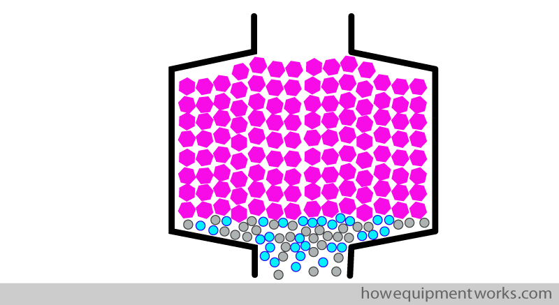
If very big granules are used, there will be enough space for the gases to pass through. However, this will reduce the surface area of the granules that will be available to combine with the passing CO2. This may lead to inadequate CO2 removal.
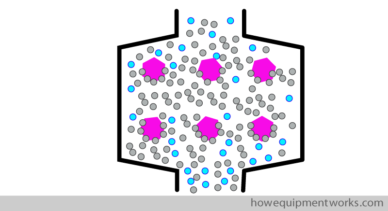
The optimum size of the granules is therefore a compromise between the resistance to gas flow and available surface area for the chemical reactions to occur. Typical diameters chosen for granules are between approximately 1.5 – 5 mm.
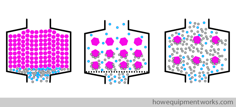
The resistance of the CO2 absorber along with the resistance due to all the tubing and valves can add to the work of breathing in spontaneously breathing patients. Therefore there is a patient weight limit, below which a circle system should not be used in spontaneously breathing patients ( please refer to your local guidelines).

Toxic reactions:
There is a possibility that under certain circumstances, toxic substances can be produced when anaesthetic agents react with the chemicals in the absorber. ( e.g. carbon monoxide , compound A). It is beyond the scope of my discussion here, and I recommend that you check the latest guidance on this issue elsewhere.
We have now come to the end of our discussion on the basics of the circle system and I hope you enjoyed it. I have another section which deals with some advanced concepts regarding circle systems. Please click here to go to “Advanced concepts of circle breathing systems explained”.

Hello! My name is Pras and I am the author of this website that you are now reading. I have made this website completely free to access so that people from all over the world can benefit from it.
If you can afford it, I would be very grateful if you would consider making a single donation of one dollar (or the equivalent in your currency) to help cover the expenses needed to run this website (e.g. for special software and computers). For this website to survive, donations are desperately needed. Sadly, without donations, this website may have to be closed down.
Unfortunately, perhaps because many people think that someone else will donate, this website gets only very few donations. If you are able to, please consider making a single donation equivalent to one dollar. With support from people like you, I am sure that this educational website will continue to survive and grow.


