We will discuss the following aspects. Please scroll down and start reading.
- Why should you understand electricity
- Current and amperes
- Potential difference and volts
- Relationship between potential difference and current
- Sources of potential difference
- Concept of resistance
- Ohms Law
- DC and AC current

Everyone wants happiness. However, according to psychologists, many of us think in certain ways which can prevent us from being happy. One may not even realise that one is thinking in such ways. The free website at the link below explains the concept of “Happy Thinking” which is about thinking in ways that help one to be happy. Once you discover “Happy Thinking” you will find yourself becoming a happier person. The website is completely free.

Why should you know about electricity ?
Electricity is everywhere. There are billions of electrons flowing all around you : in operating room lights, anesthesia monitors , diathermy , ventilator controls, syringe pumps, the computer screen that you are reading now and so on and so on …..
The amazing image below shows a picture of earth taken at night from outer space. The street and house lights illuminate the countries and give an idea of how widespread the use of electricity is all over the world. In the image below, how lit up is your country ?

Learning a bit about electricity is useful because:
- It will provide the basics for understanding electrical safety.
- It will help you to better understand the principles of electrical medical equipment such as electrosurgical devices, defibrillators, temperature measurement etc.
Electrical current and ampere
One often hears the words “current”, “voltage” and “resistance”. It is very important to understand these three concepts well. Let us start by explaining what electric current is. Let us imagine that an electrical current is going through the light brown wire below.
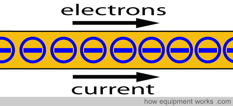
When we say that an electrical “current” is flowing, what is it that is actually flowing ? Current is the flow of electrons. Electrons can be thought of as negatively charged “particles”. The movement of these electrons is called current.
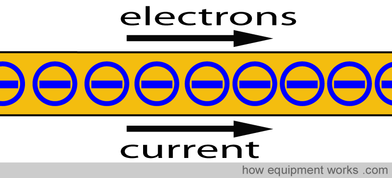
Current is measured in units called ‘amperes’. The number of amperes in a wire relates to how many electrons pass a cross section of the wire per second.
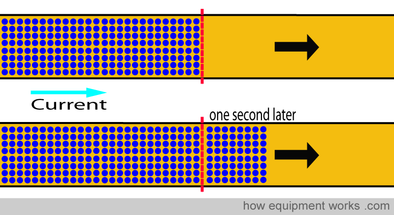
A current of one ampere relates to a certain number of electrons passing a cross section of the wire in one second. This number is absolutely huge, and please don’t bother to remember it. The wire below is carrying one ampere of current.
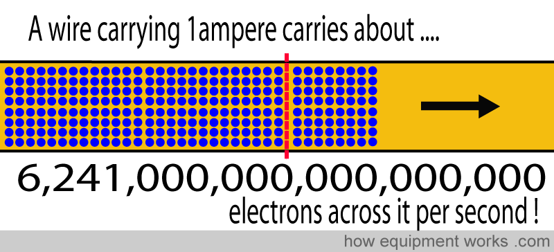
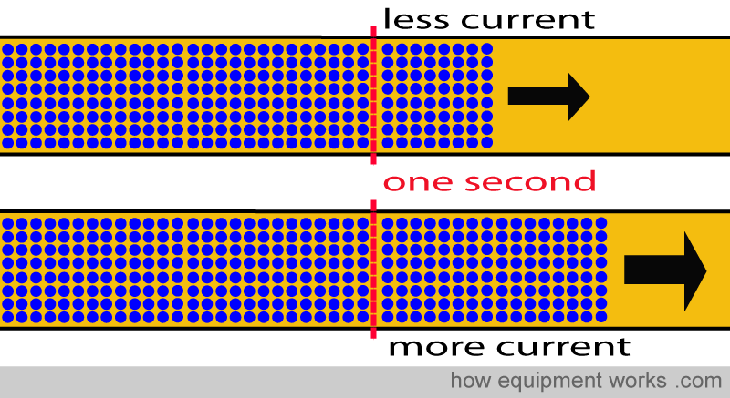
Higher the current (higher amperes) higher is the number of electrons that pass a cross section of the wire per second.
In reality, it is really tough to count zillions of electrons.

Since it is so difficult to count so many electrons, the official definition (“International System of Units”) of the ampere relies on a more “practically measurable definition” . To you and me (non physicist), even this definition would still appear very impractical, but at least you don’t have to count individual electrons. The ‘practical’ definition is given below, but please don’t memorize it (unless you are gifted with an unlimited memory capacity).
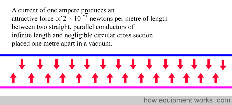
So in summary, ampere relates to the amount of electrons flowing across a wire per second.
Potential difference and volts
It is common knowledge that water and electricity don’t mix very well!

However, interestingly, water and electricity behave in a ‘sort of similar’ way. Since, unlike electricity, water is visible, it often useful to first understand the behavior of water and then using it to understand electricity.
So now let us imagine that you want to install a beautiful waterfall in your garden (also imagine that you are rich enough to have a big garden).

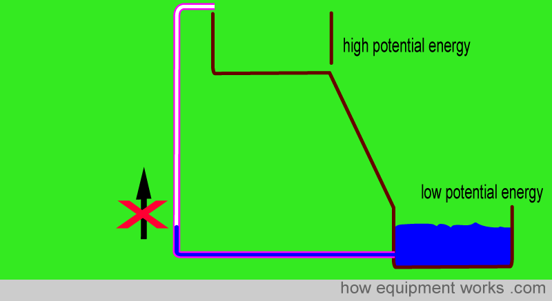
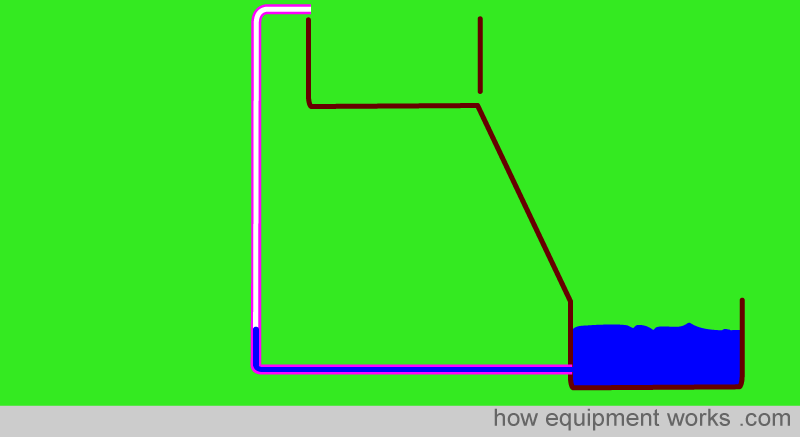
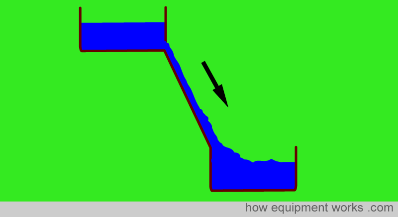
To save money, you decide to build, by yourself, what you think is a waterfall. It looks like this.
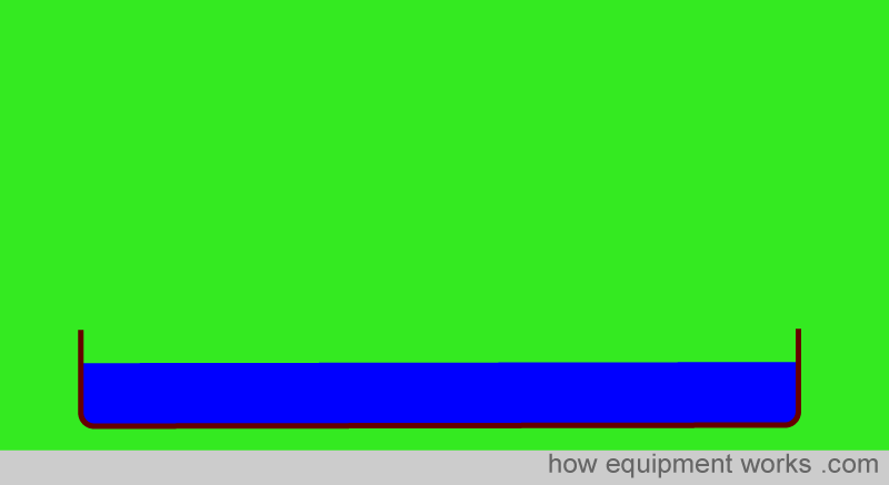
Unfortunately the water doesn’t flow at all. You cannot understand why.
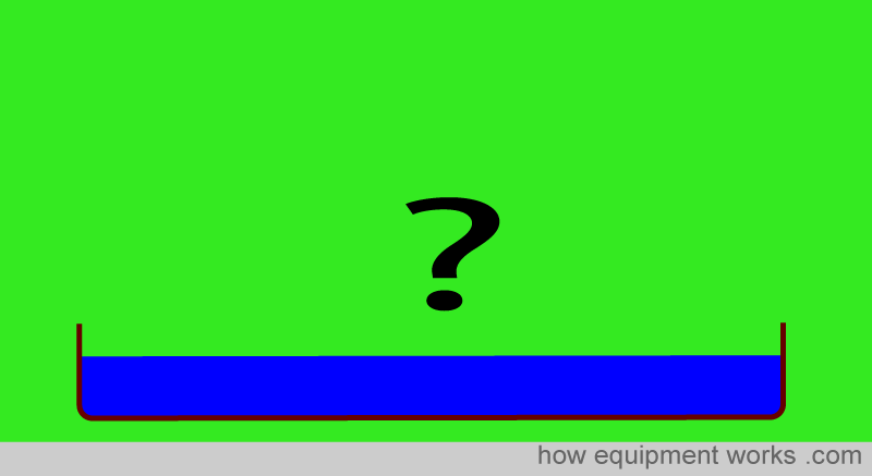
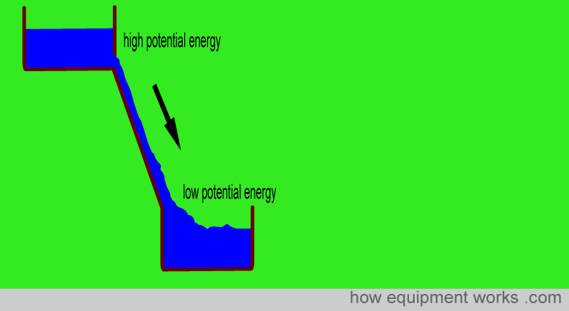
The reason why there is no water flow is that there is no energy difference in the flat pond. For water to flow, there needs to be a difference in energy between one area and another. Then the water will flow from the area with high energy to the area with low energy. In the case of a waterfall, this energy can be given by elevating one part of the water. The elevated water has more energy (due to gravity) than the water at the base, making water flow.
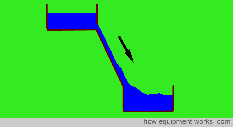
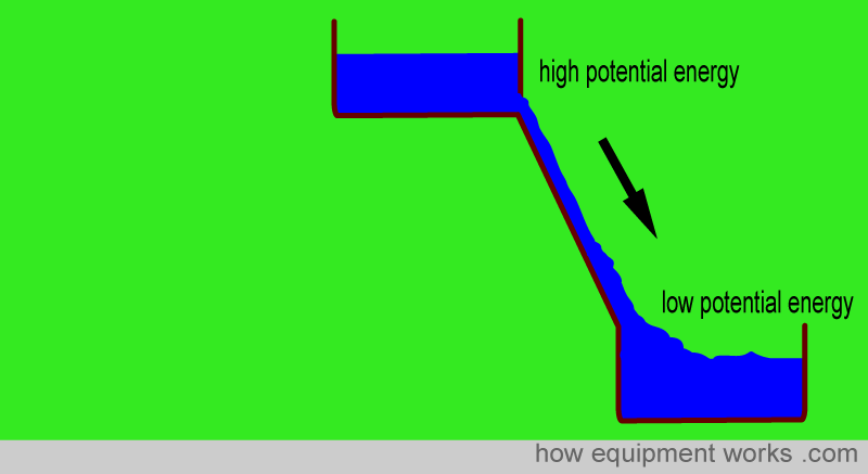
Let us examine this in terms of energy. In the case of the waterfall, it is gravity that determines energy. Higher the water, higher is the potential energy it has. In our waterfall, the higher tank has a higher potential energy than the lower tank which has a lower potential energy and this difference in energy makes the water flow. As the water flows down the waterfall, it loses potential energy. Once it reaches the lower tank, it has a lower potential energy than the higher tank.
Once the top tank is empty, of course water wont flow back upwards on its own. This is because water does not flow from an area of low potential energy to an area of high potential energy.
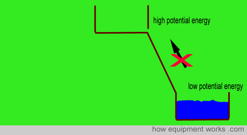
For the same reason, if you simply connected a pipe from the lower tank to the upper tank, the water won’t go back to the higher tank.
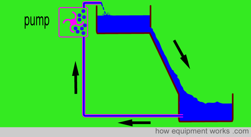
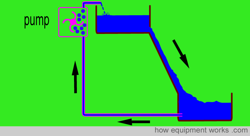
If we want our garden waterfall to keep working we need to make water return to the upper tank. For this, we need to provide energy to the system. This is possible with a water pump. Water in the upper tank has a high energy and as explained before, it flows down, giving up energy in the process. The pump then “provides energy to drive the system” by taking the water with lower potential energy and pumping it up to the upper tank. The water that has reached the higher tank now has a high potential energy and is able to flow down again, repeating the cycle again and again. Now we finally have a beautifully working garden waterfall that keeps on flowing.
Now let us move to something electrical. Instead of having a waterfall, let us imagine that we want to light up a light bulb. A light bulb is something that lights up when current passes through it.
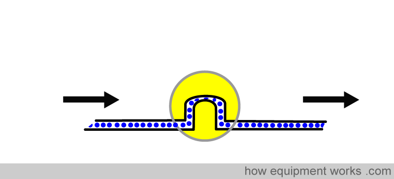
Let us connect up some wires to the bulb to try and make it light up. But sadly, we find that the bulb does not light up. We can see that the wire has electrons in it, but the bulb does not light up. Why is this ?
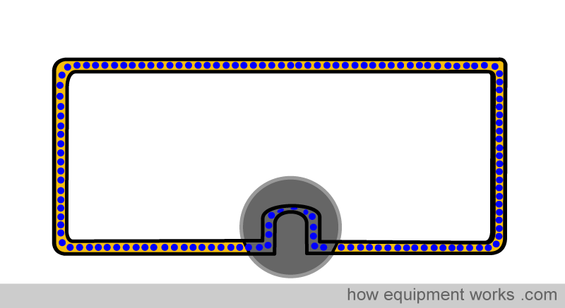
The reason that the bulb does not light up is that there is no “flow” of electrons. Electrons need to move in one direction to make the light bulb light up. If they just ‘hang around’ without moving in one direction, nothing happens.
Let us see the wire in close up to see why the bulb is not lighting
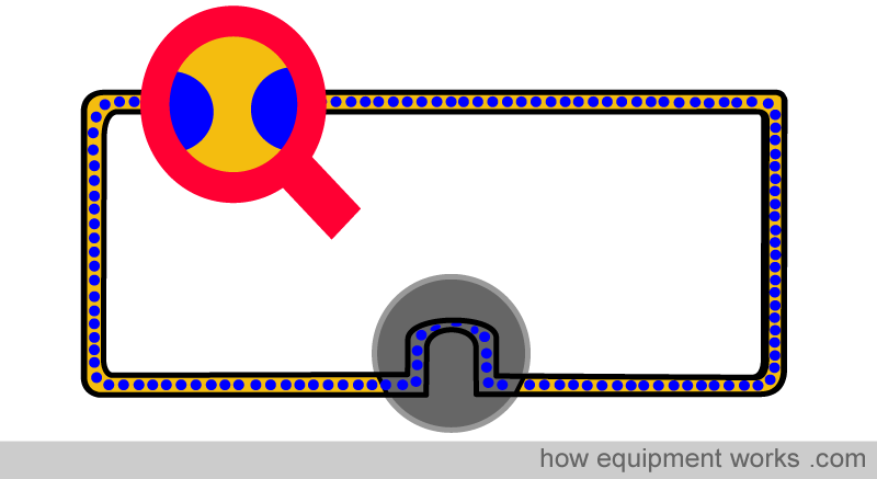
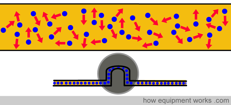
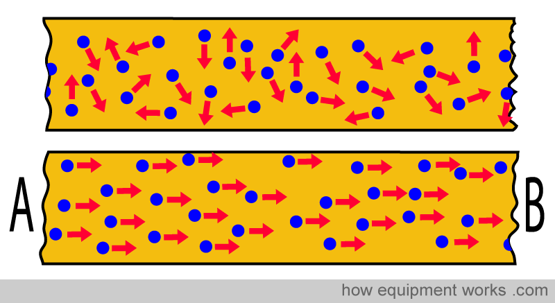
You will see that the electrons in the wire are moving randomly in all directions. However, it is important to note that they are NOT moving in one particular direction, are simply ‘hanging around’. You will recall that current is the flow of electrons in a particular direction. So in our example so far, since the electrons in the wire are all not flowing in a particular direction, there is no current passing through the bulb, and hence the bulb does not light up.
This is similar to the situation where the waterfall did not work without a pump.The waterfall system has water, but the water is not moving in a particular direction, due to the lack of energy.
In the waterfall, you will recall that a pump was necessary to provide the energy difference for the water to flow.
Just like the water in the waterfall, electrical circuits need a potential energy difference to make the electrons flow.
The image below shows two wires. The upper wire has no potential difference across it. The electrons are randomly moving in all directions with no flow in one particular direction. Therefore this wire is not carrying any current. The lower wire has a potential difference across A and B. It makes the electrons flow in a particular direction and therefore this wire is carrying a current.
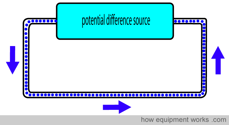
There are a variety of sources that can produce a potential difference that can make a current flow in an electrical circuit. You can think of a ‘potential difference source’ as being like the pump in the waterfall we discussed. The pump makes water flow around the system. In an electrical circuit, the potential difference source makes the electrons (i.e. current) flow around the circuit.
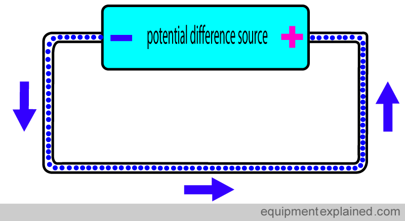
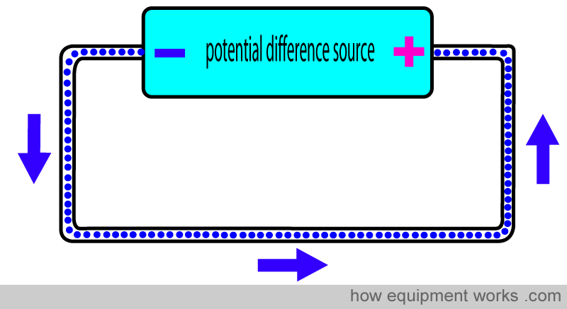
Potential difference sources have a ‘ negative pole’ and a ‘positive pole’. Current leaves the negative pole and returns to the positive pole.
As mentioned before, there are many types of potential difference sources, and many of these will be discussed later. For now, let us discuss a common potential difference source that you may have used at home and hospital. This source is the common disposable battery. You may have put these in the clocks in your home. Most laryngoscopes use these batteries to power the light bulb.
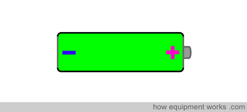
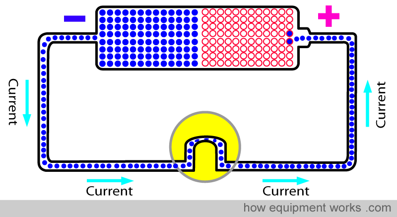
Let us now connect this battery to the bulb we were trying to light up before. The potential difference generated in the battery makes the electrons move. The current goes from the negative pole, through wires to the bulb, goes through the bulb and makes it light up, and returns by wire to the positive pole.
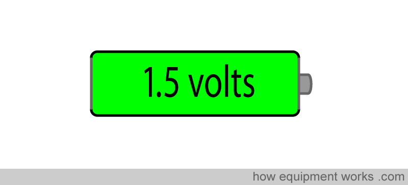
The unit of measurement for potential difference is “volt”. More the potential difference across the poles, more is the volts.
A typical house hold battery has 1.5 volts, or abbreviated as “1.5 V “
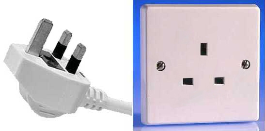
On the other hand, potential difference coming out of wall sockets can be quite high (e.g. 120 volts or 230 volts).
Now I must confess that drawing all this stuff can be quite tiring. Fortunately, when discussing electricity, one doesn’t have to draw the “real” thing all the time. Instead, one can use symbols. For an example, the symbol for a battery is:
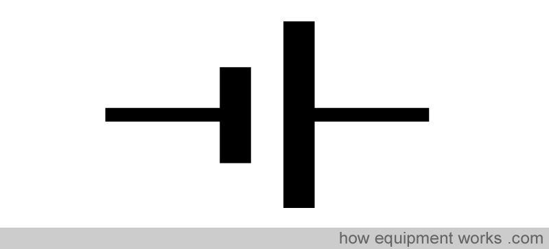
The shorter vertical line represents the negative pole.
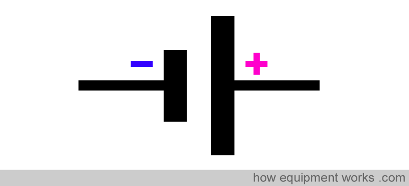
A way to remember which vertical line is negative and which one is positive is to remember that ‘ n ‘ is shorter than ‘ p ‘.

Similarly, a light bulb can be represented by a symbol.
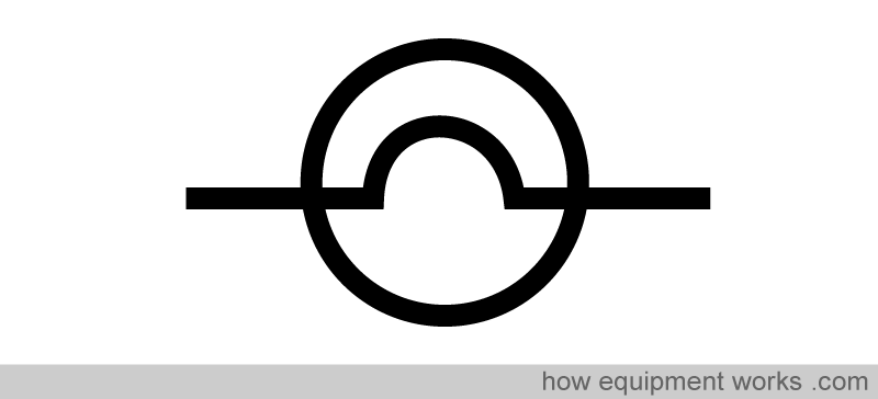
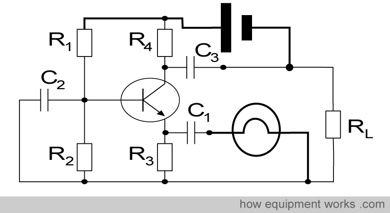
You will see that electrical circuits can be drawn much more easily using symbols than using realistic diagrams. For an example, this circuit ….
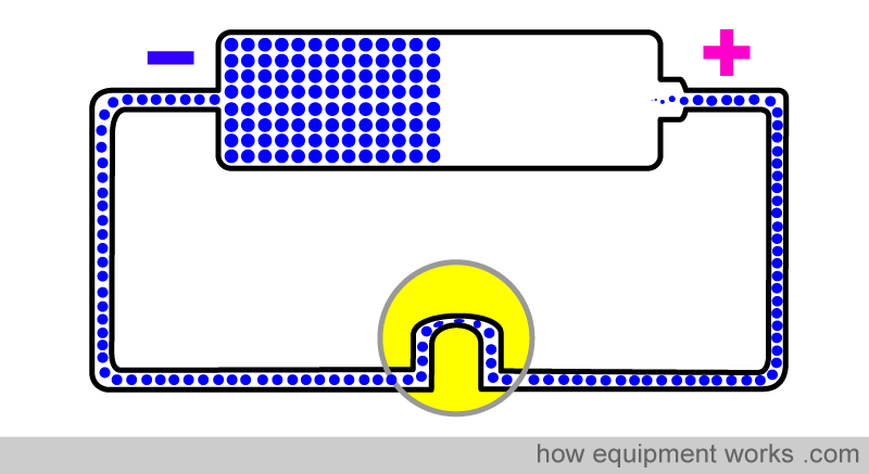
… can be easily drawn as ….
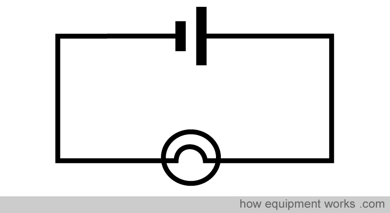
In practice, real medical equipment circuits can be very complex and the use of symbols becomes very convenient. Below is a very simple (for engineers ! ) electrical circuit drawn using symbols.
Relationship between potential difference and current.
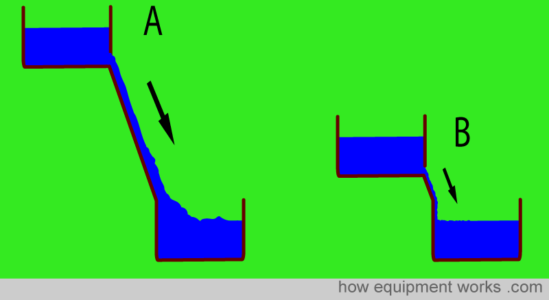
Now let us return to potential difference and current. Recall that current is the flow of electrons. Potential difference is what makes electrons, and therefore, current flow. In our waterfall example, we said that potential difference was like the difference in height of the higher and lower tank, and the difference made the water flow.
Take the two waterfalls below. Waterfall A has a large difference in height whereas waterfall B has small difference in height. Waterfall A has a higher energy difference than waterfall B and therefore the flow rate in waterfall A is much faster than waterfall B. In other words, water flow rate is proportional to the energy difference.
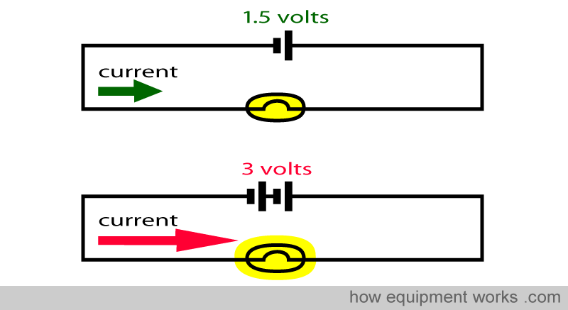
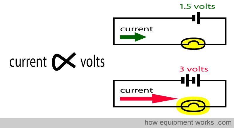
This is the same in electrical circuits. If you increase the potential difference, more electrons will flow. Take the example below. In the top circuit, the potential difference is 1.5 volts and this results in a certain current flow. In the bottom circuit, the potential difference is doubled to 3 volts. This doubles the current flow, making the bulb light up brighter.
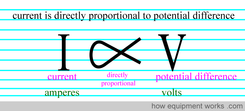
There is a famous electrical law called “Ohms Law “. While Ohms Law will be explained in a bit more detail later, what we have already discussed forms “PART “ of this law.
I.e. Part of Ohms Law states that “for a given wire (conductor), current flow is directly proportional to the potential difference across it. “
Sources of potential difference
There are many sources of potential difference.
Single use batteries :
So far in our discussions we have used batteries as our source of potential difference. We will discuss batteries first and then other sources of potential difference.
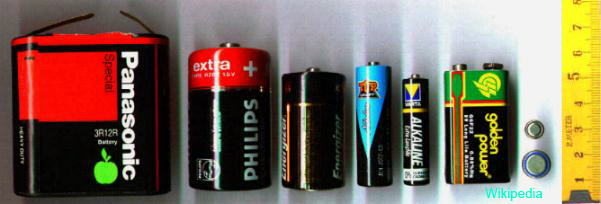
Batteries are used frequency at home to power small items such as clocks. In hospital, laryngoscope bulbs are typically powered by batteries. Batteries come in all sorts of shapes and sizes.
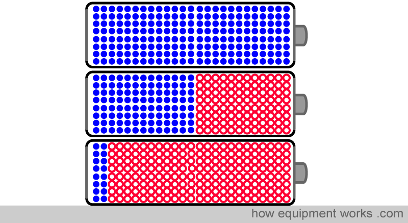
In batteries, a chemical reaction generates the potential difference. Once the chemical reaction has “finished”, the battery no longer generates a useful potential difference and the battery is thrown away.
Rechargeable batteries :
These batteries have chemical reactions that are “reversible”. If you apply a potential difference and current to a rechargeable battery, chemical reactions in the battery “store” this energy. When energy is required, the further chemical reactions are able to release the previously stored energy. These batteries can be recharged many times are economical in the long term. Rechargeable batteries are very frequently used in household products such as mobile phones and laptops. They are also very frequently used in many hospital devices such as syringe pumps, portable monitors, defibrillators, motorised operating tables etc. It is extremely important to keep devices using rechargeable batteries “charged”. If you don’t keep things correctly charged (e.g. forgetting to plug the device to a wall power outlet) the batteries may run out early and unexpectedly shut down a piece of critical equipment, such as a syringe pump during a patient transfer.

Electrical Generator:
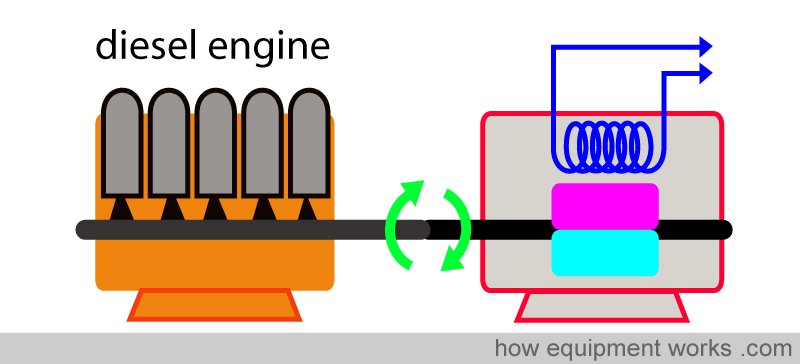
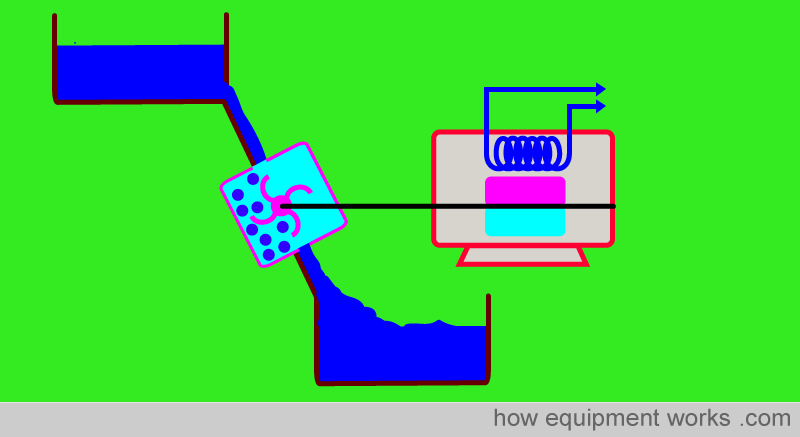
Power to our homes and hospital comes from huge electrical generators. These are devices that convert rotating motion to electricity.
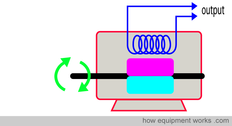
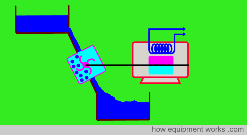
There are many different ways you can provide the rotating motion to the generator. For example, water in a dam can be used to turn the generator (hydroelectric power).
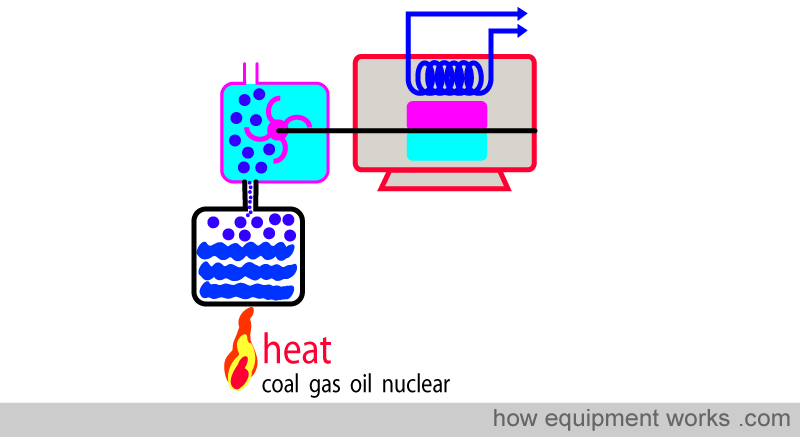
Many power stations use steam to turn the generator. The steam is made by heating water, which can be done by energy sources such as oil, gas, coal, or nuclear power.
Many power stations are connected to each other by a network of wires called the “electrical grid “. The grid allows the system to share resources and provide backup power if one power station fails. The grid distributes power to hospitals, homes and other consumers.
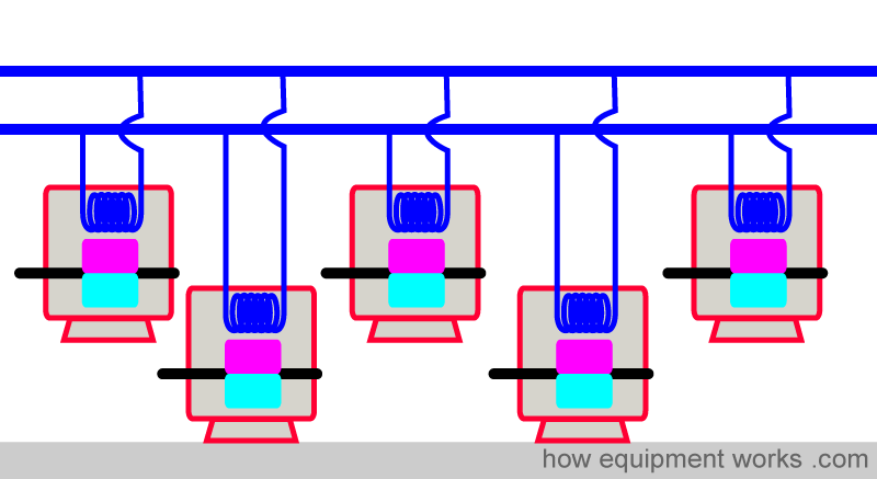
The grid is carefully controlled to meet the electricity demands of the consumers. For an example, grid engineers study television programs closely because they know that when popular television programs end (e.g. after an important sporting event) , millions of people get up and heat water in electric kettles for coffee or tea. Grid engineers plan for this and rapidly activate special power stations that can boost electricity supply to the grid quickly to meet this demand. For example, during the Royal Wedding in the United Kingdom, the electricity demand increased by 2,400,000 watts which is the equivalent of nearly one million kettles being turned on at the same time.

Emergency Generator:
Like everyone else, hospitals also get their electrical supply from the electrical grid. If the grid fails to deliver power, critical patient support equipment such as monitors, ventilators, anesthetic machines, etc. may stop functioning. For this reason, hospitals have their own emergency power supplies. For brief periods of power failure, huge rechargeable batteries are able to supply the necessary power. For longer periods, the hospital will have a generator which is usually turned by a diesel oil engine. This generator comes on automatically when a power failure is detected.
Concept of Resistance
In the world of electricity, there are three friends that are always present together and affect each other. We have already discussed two of them, i.e. current (amperes) and potential difference (volts). Now let us discuss the third friend, called resistance,

In a circuit, electrical resistance is something that “resists “ the flow of electrons (i.e. resists the flow of current). Let us go back to our waterfall example. However, we now replace the waterfall with a pipe that connects the two tanks. The water flows in pipe from the higher tank to the lower tank due the difference in potential energy.
Let us now take two such arrangements. In both, the water tank height is the same. I. e, both systems have the same potential energy. However, arrangement ‘A’ has a narrow pipe and arrangement ‘B’ has a wide pipe.
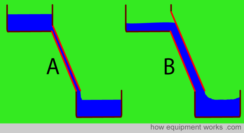
The flow rate of water in pipe A is slower than the flow rate of water in pipe B. This is because pipe A, being narrower has a higher resistance to water flow than the wider pipe B.
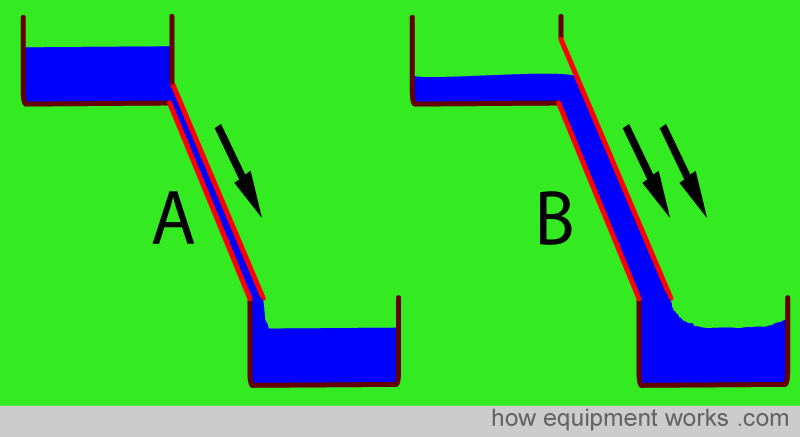
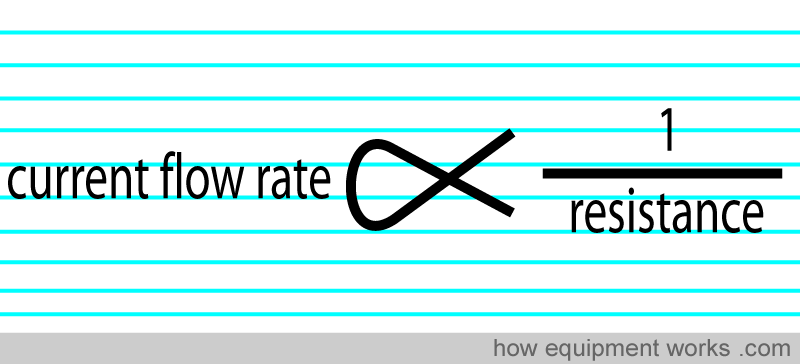
So in the above example, flow rate and resistance have an “opposite” relationship. When one increases, the other decreases. In more technical language, we can say that the flow rate is inversely proportional to resistance.

Electricity is similar. Let us take a wire and light bulb connected to a potential difference of 1.5 volts. This potential difference makes current flow in the wires and light bulb.
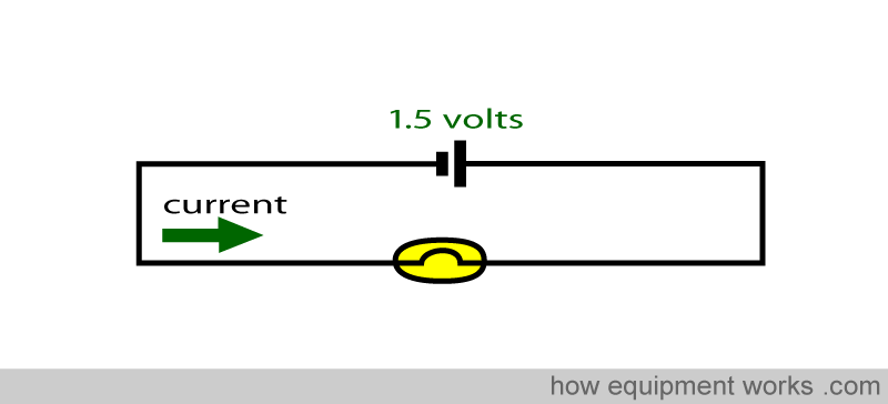
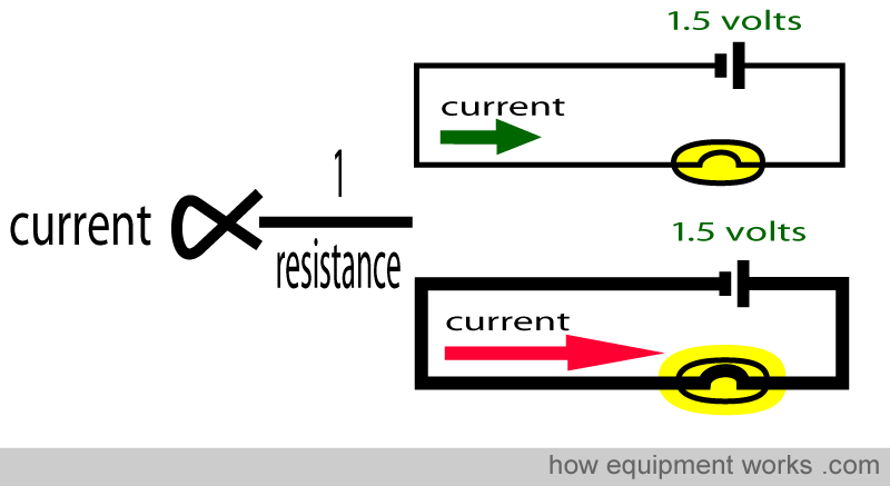
Suppose we now make two similar electrical circuits with batteries, wires, and light bulbs. In both circuits, we keep the potential difference the same. (1.5 volts). However, in one circuit we use thin wires with a high resistance and in the other, we use thick wires with a low resistance. It will be seen that more current flows (brighter bulb) in the low resistance thick wires than the thin high resistance wires.
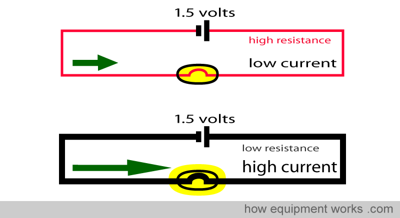
So, high resistance results in a low current flow, and conversely, low resistance results in an high current flow. We can put this into an equation where current flow is inversely proportional to the resistance of the wire it is traveling in.

Everyone wants happiness. However, according to psychologists, many of us think in certain ways which can prevent us from being happy. One may not even realise that one is thinking in such ways. The free website at the link below explains the concept of “Happy Thinking” which is about thinking in ways that help one to be happy. Once you discover “Happy Thinking” you will find yourself becoming a happier person. The website is completely free.

Ohm’s Law
A while ago we saw part of Ohms Law which stated that the current flow across a wire is directly proportional to the potential difference across that wire.
And more recently we learnt that current flow is inversely proportional to resistance.
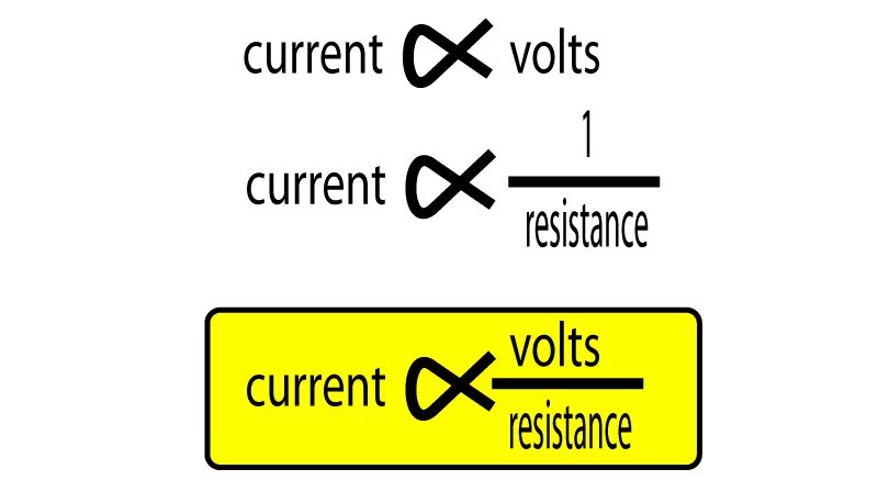
Now you are ready for the “full “ Ohms Law ! Let us combine the two relationships you just learnt.
Ohms Law states that:
Current flow through a conductor (wire) between two points is directly proportional to the potential difference across the two points, and inversely proportional to the resistance between them. The Ohms Law can be shown by the equation in the yellow box.
So you can see that the three friends, volt (potential difference), resistance and current are best of friends. And just like friends, if you get two together, they will talk about the third friend.
Similarly, by rearranging the Ohms Law equation, if you know two of the values, you can find out what the third one is.
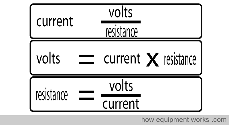
It is time to use the international abbreviations in the equations. Note that the international abbreviation of Current is not ” C “. Instead , it is ” I ” (capitol i ). This bizarre abbreviation has to do with history, where current used to represented in the French language.
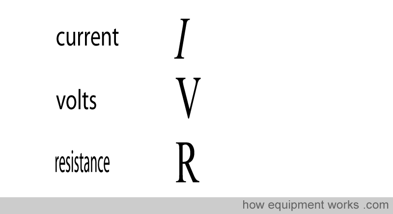
Now here are the equations we saw before, using the abbreviations.
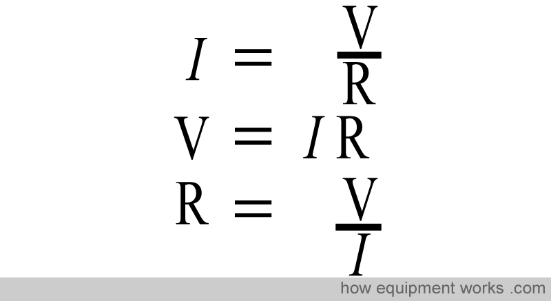
You don’t need to memorize all the above three equations. Just remember one, and you can work out the rest when needed.
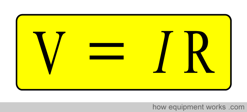
Ohms Law is a very important law in the world of electricity. It was discovered by Mr. Ohm.

The unit of resistance is named after him. The unit of resistance is called “Ohm” and its symbol is shown below.

Let us take an example of Ohms Law in clinical practice.
Let us imagine that you have attached electrocardiogram (ECG) leads to your patient. You then plug the ECG lead plug to its socket in the monitor.
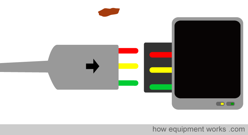
Unfortunately, as you are doing this, a piece of dirt gets into the plug. This makes the yellow wire have a poor contact with its counter part, increasing its resistance.
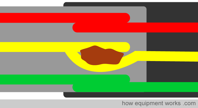
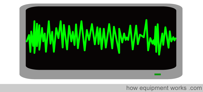
According to Ohms Law, the high resistance affects the voltage and current in the wire, disturbing the ECG tracing.
The plug is unplugged and the dirt removed. Now the contact is good and the resistance is now low.
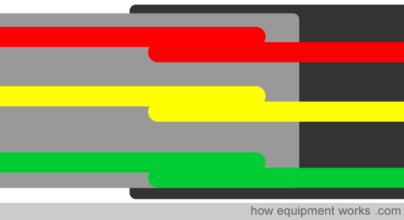
Low resistance makes the current flow easily and you get a much better ECG tracing.
DC and AC current
You will recall that current is the flow of electrons.
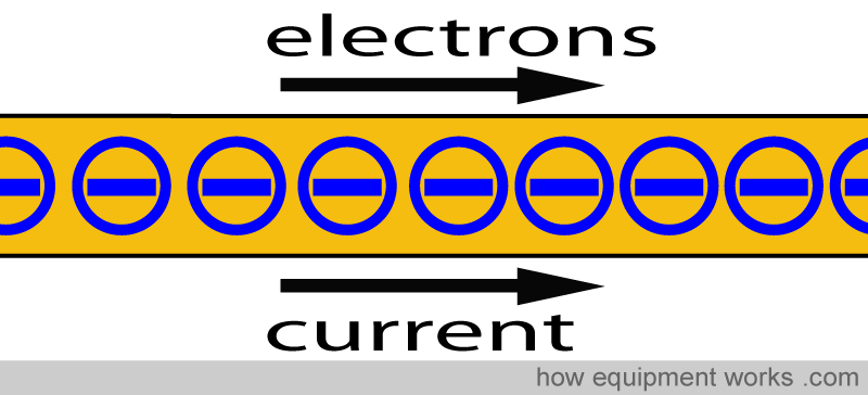
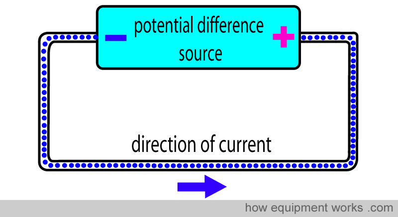
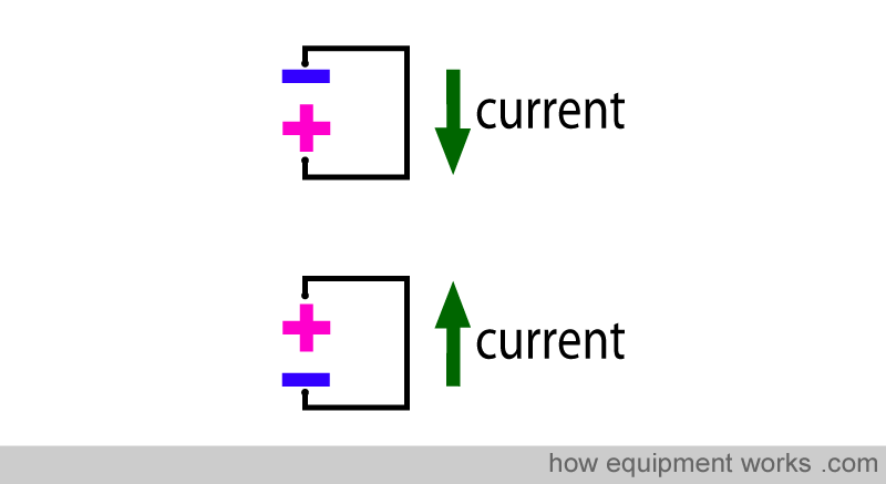
The electrons (i.e. current) flows from the “negative” pole to the “positive” pole. Current therefore has a “direction” of flow.
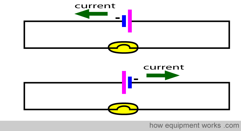
The direction of the current will change if the negative and positive poles of the source are exchanged.
There are two main types of current flow : “Direct Current (DC) and Alternating Current (AC).
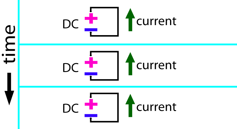
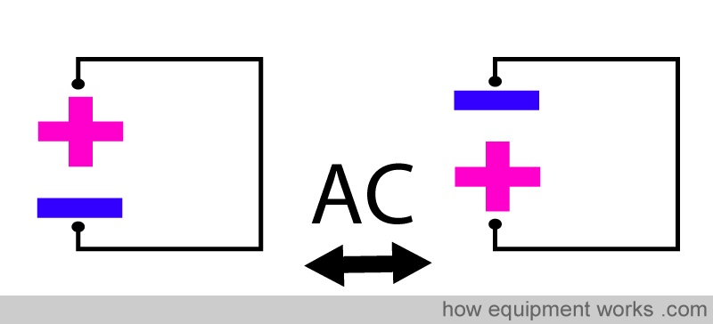
Basically, in DC, the “direction” of current flow remains constant over time, whereas, in AC, the direction of flow of current keeps alternating from one direction to the other. Let me try and make things clearer for you.
To make the diagrams a little less crowded, I have simplifying them a bit. The potential difference source is represented with a minus and plus sign. The green arrow will show the direction of current. Remember, current always flows from negative to positive.
I will now describe to you the difference between DC and AC. Let us start with DC. Below is a series of images showing a circuit with a DC power source. The repeated images show you what happens over a time period. You will notice that over time, that the current has NOT changed direction (green arrow remains in the same direction). This is the fundamental property of DC: the current does not change direction.
AC is quite weird when compared to DC current. In AC, the negative pole and positive pole of the source exchange themselves repeatedly.
Since current travels from negative to positive, this means that the current also changes direction repeatedly.
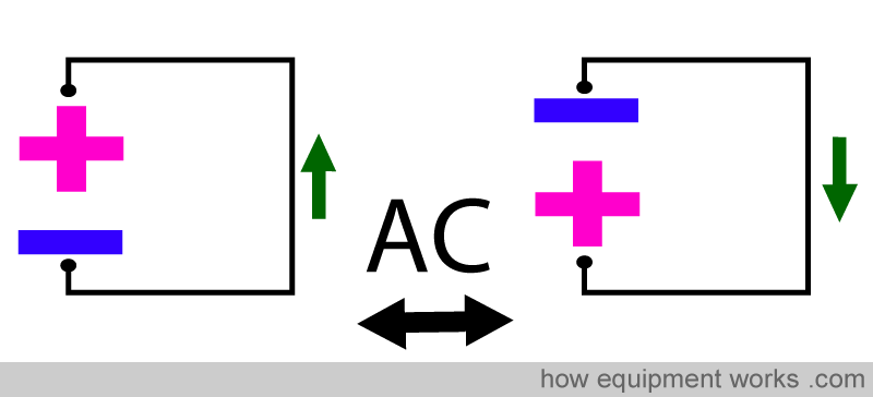
The series of images below show AC over time. The positive pole and negative pole keep alternating. In response to this, the direction of current also keeps changing repeatedly.
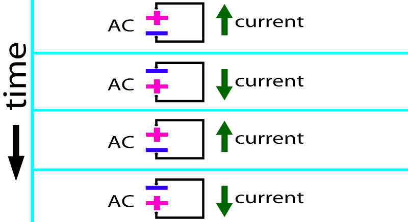
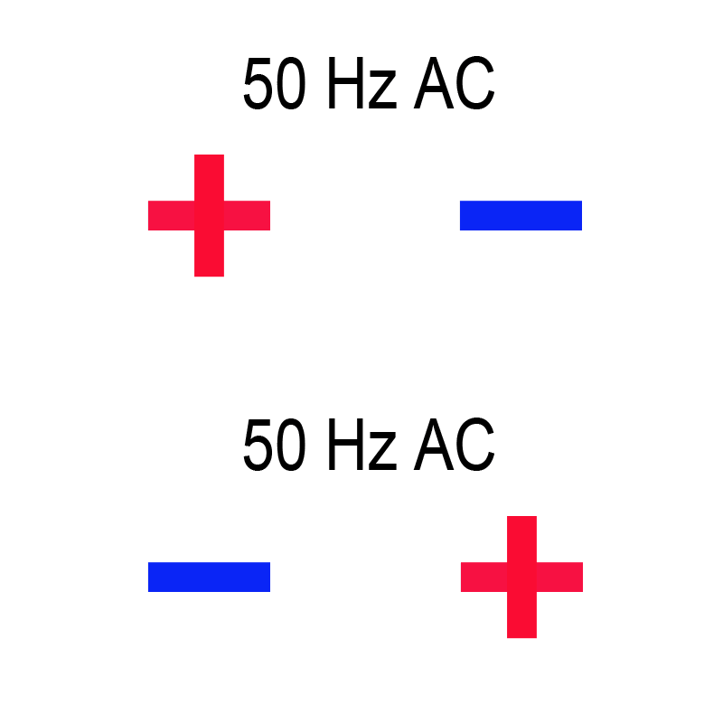
This repeated alternating of current direction happens quite fast. In many countries , it happens 50 or 60 times a second (i.e. frequency of 50 Hz or 60 Hz). For an example, in the USA, it happens 60 times a second (60 Hz) and in the United Kingdom, India and Sri Lanka, it happens at 50 Hz. The animation below may help you to appreciate how rapid this is. The negative and positive poles alternate 50 times second. If you suffer from photosensitive epilepsy, please skip this animation.
You may wonder why someone would produce a weird current in the form of AC. There are good engineering reasons why we have AC, and this will be discussed later on. For now, we will continue our discussion about the way AC behaves.
Before proceeding further, let me introduce you to a scientific instrument called an ‘oscilloscope’. An oscilloscope has a screen that shows voltage changes over a time. The vertical axis represents voltage and the horizontal axis represents time. This helps us to visualise how current behaves over time, and will be very useful when we continue our discussion on AC and DC.
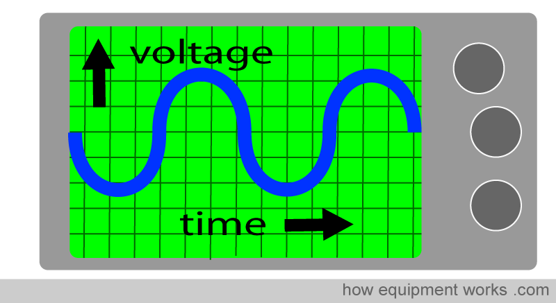
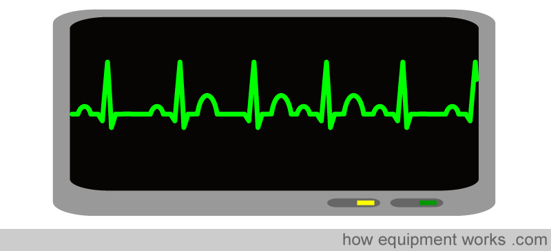
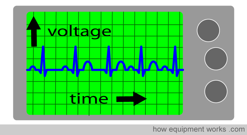
If an “oscilloscope” sounds complicated, don’t worry because I am sure you have used one everyday in your professional life. An ECG (EKG) monitor is a type of oscilloscope. It measures the potential difference of the heart over time. Looks familiar ?
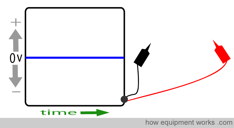
Below is a simplified oscilloscope. Right now, nothing is connected to the oscilloscope probes (black and red probes) and therefore the the tracing (blue line) remains on the baseline.
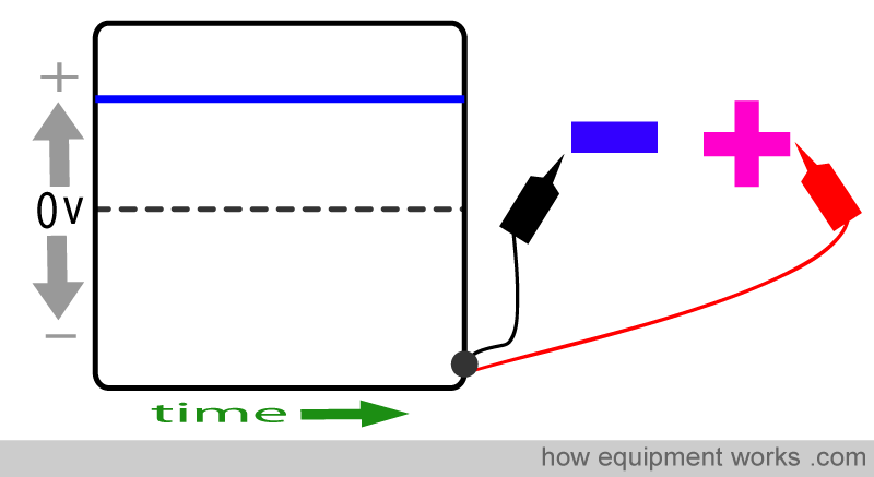
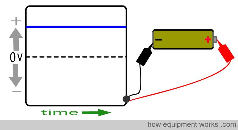
Let us connect the oscilloscope to a DC source. The oscilloscope shows a straight line reading (blue line) above the baseline (broken line).
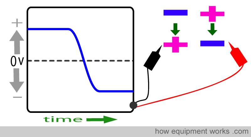
Oscilloscopes show change in direction of current flow by the trace crossing the baseline. Let us reverse the plus and minus poles of the source (i.e. we change polarity). You will see that the trace crosses the baseline from the top to the bottom.
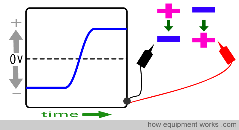
Let us change the polarity again, so it is back to how it was before. Again you will that the oscilloscope shows this change by making the tracing cross the baseline, in this case from the bottom to the top.
Now let us examine DC and AC current using an oscilloscope.
We first connect it to a DC source such as a battery. You will get a steady tracing above the baseline. Since with DC, the direction of current flow does not change, the tracing does not cross the baseline.
Now let us examine AC with the oscilloscope. You know that, unlike DC, the polarity of AC keeps changing, so you would expect to see something like this.
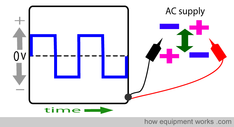
However, the above square waveform is NOT what you see. Instead you will see a waveform that has much more graceful curves, as shown on the oscilloscope on the right below.
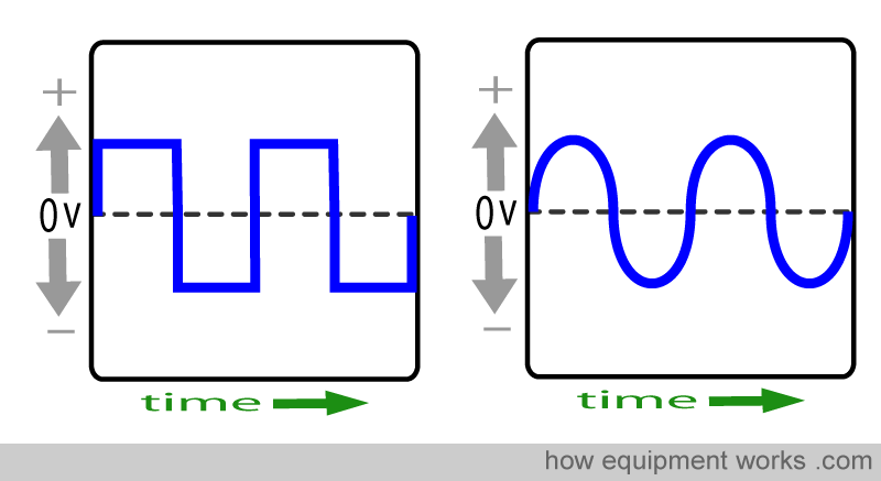
The reason why you see the graceful curves instead of the sudden square changes is because the polarity in AC does NOT change suddenly as shown below.
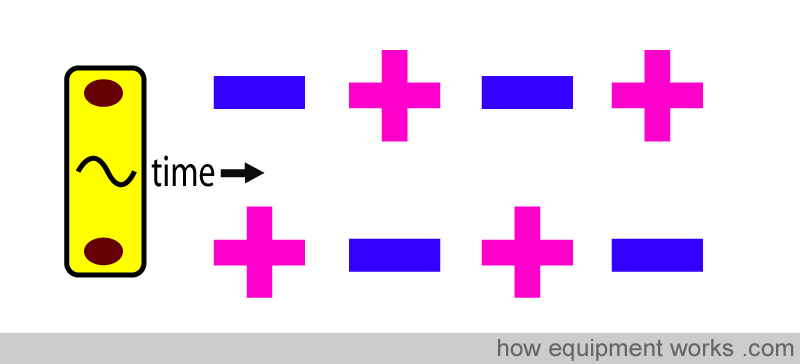
Instead, the change in AC happens “gently”. The potential first starts to decrease and eventually becomes zero. Then the polarity gets reversed and potential difference starts to rise till it reaches the maximum. The changes in polarity continue in this fashion.
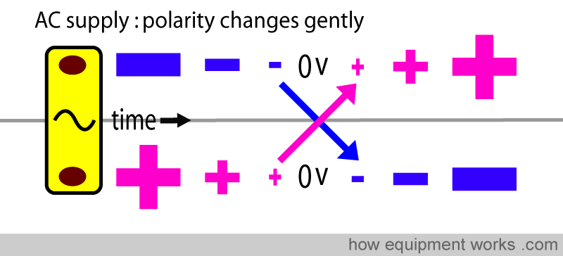
This gentle change in polarity ( as shown in the “polarity dance”) below accounts for the nice curvy AC oscilloscope tracing.

You are now ready to see how the ‘curvy waveform’ oscilloscope tracing of AC is formed. (This is the waveform that you often see in text books)
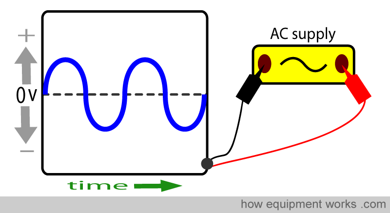
I will now show you how the “gentle” transition shown below becomes the curvy waveform seen with AC.
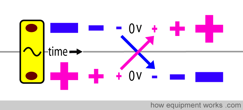
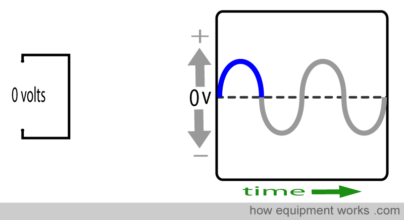
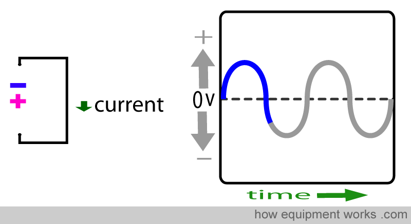
The above transition will be shown in a step by step manner. As each step is shown, you will see the AC wave form in the oscilloscope.
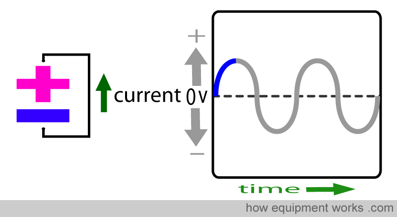
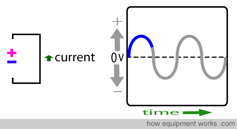
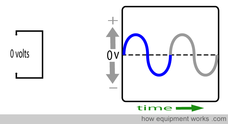
Note that AC has periods where there is no current flow.
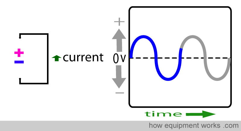
The change of polarity causes the tracing to cross the baseline.
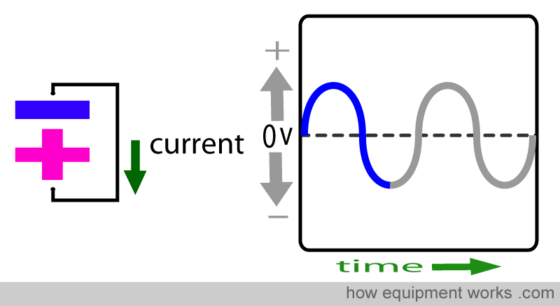
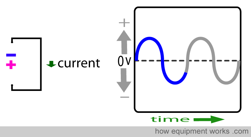
And the cycle repeats itself.
You would have noticed that AC has periods where there is zero potential difference. During these times the current flow is zero.
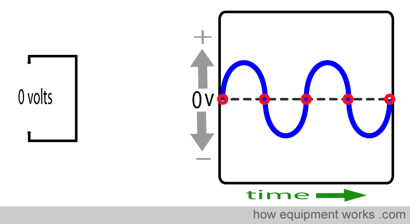
Normally one does not notice these zero periods because they happen so fast. However, sometimes you can see these off periods in fluorescent lights (tube lights). The off periods may make the light flicker (faster than what is shown below, the computer animation is not fast enough).

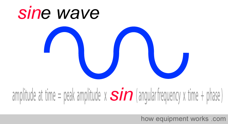
In physics, the curved waveform of AC can be described as being a “sine wave”. The mathematics of such a wave are described by a “sin” function in the complicated equation shown below, which I hope you will not memorize.
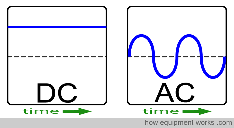
Just to recap, the image below shows a DC waveform and an AC waveform together for comparison.
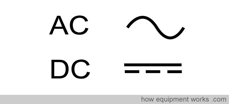
Below are commonly used symbols to represent AC and DC power supplies.
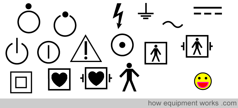
If you look around you will discover that your world is full of symbols. When you are bored have a look around your operating room and you will find plenty of hidden symbols. Typically they will be found on electrical equipment. Look where monitoring leads and power leads connect.
Why are our homes and hospitals supplied with AC and not DC ?
The electrical current that comes out of the wall sockets in homes and hospitals is mostly AC. AC looks more complicated than DC, so why do they use AC to power our hospitals and homes ?
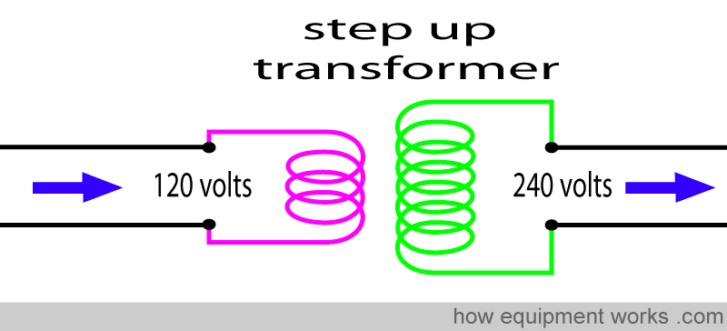
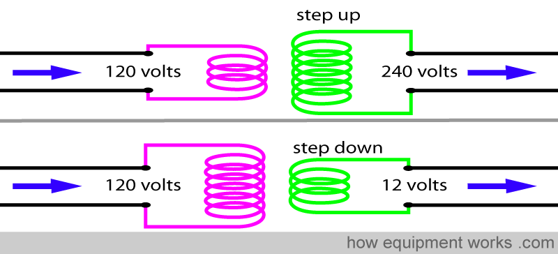
To explain why AC and not DC is supplied to your hospital and home, you need to understand how a device called a “transformer” works. A transformer “transforms” voltage to a higher voltage or a lower voltage. If it transforms the input voltage to a higher output voltage, it is called a “step up” transformer.
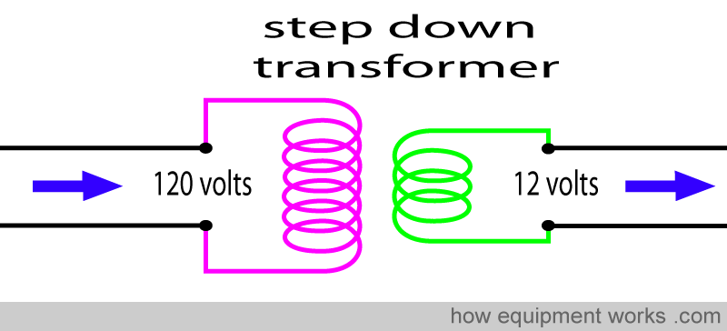
If it transforms the input voltage to a lower output voltage,it is called a “step down” transformer.
Let us see how a transformer works. The transformer uses two very important properties in the world of electricity.
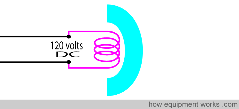
The first phenomenon used in transformers is that when a wire carries an electric current, it generates a magnetic field.
In the example below, the wire (coil) is carrying direct current (DC) . The magnetic field is shown as a blue arc.
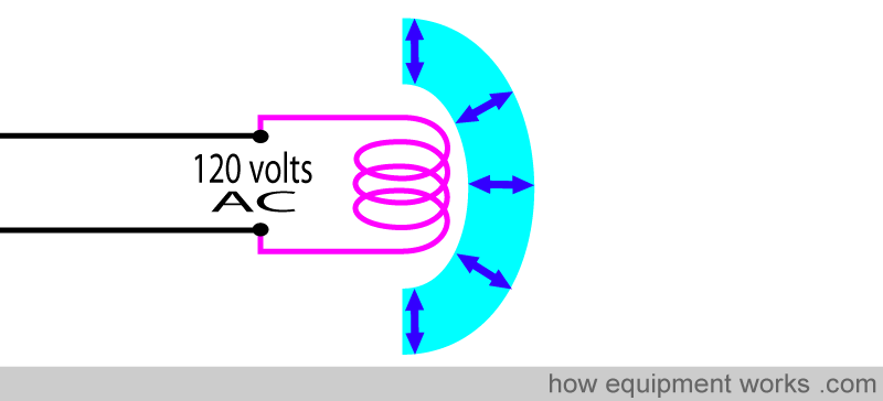
Below, we demonstrate a wire coil carrying alternating current (AC). It is important to note that, since the current is changing direction, it produces a “changing” magnetic field (shown by blue arc with arrows). I.e. In DC the field is non changing, whereas in AC the field is changing all the time.
Now let us discuss the second electrical phenomenon that makes transformers work. It is called “electromagnetic induction” and let us take a coil of wire to demonstrate it.
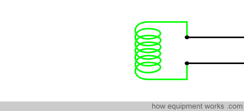
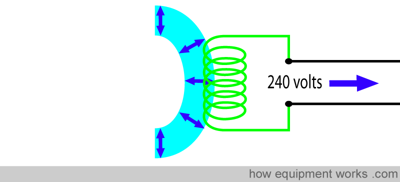
Electromagnetic induction refers to a phenomenon where if a wire (or coil of wire as in our example) is exposed to a CHANGING magnetic field, a current will be induced in the wire. In the example below, the changing (i.e. repeatedly increasing and decreasing) magnetic field is represented with the blue arc with arrows.
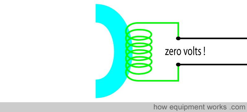
It is important that the magnetic field is changing. A non changing magnetic field (as shown below) will NOT induce a current in the coil.
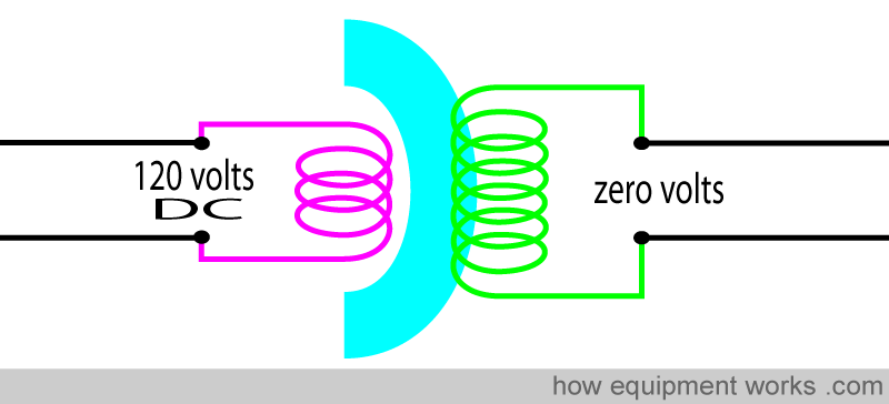
Now we can explain how the transformer works. The input AC goes into the primary coil (pink). This produces a changing magnetic field (blue arc with arrows). The changing magnetic field induces a current in the secondary coil (green) and in this way, electric energy is transferred from the primary coil to the secondary coil.
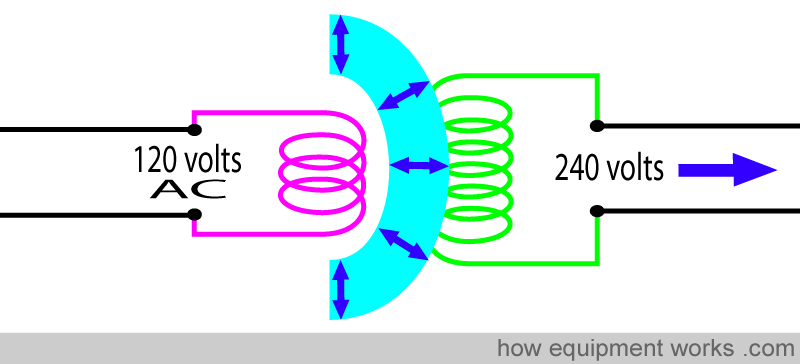
At this point you can see that a transformer works only with AC, because it needs a changing magnetic field to transfer energy across it. If you used DC, the transformer would not work. The magnetic field would be non changing and thus would not transfer energy across to the secondary coil.
Whether the transformer behaves as a step up or a step down transformer depends on the ratio of the loops in the primary coil and secondary coil. In a step up transformer, the secondary coil has more turns than the primary coil. Similarly, in a step down transformer, the secondary coil has less turns than the primary coil.
Now we understand that transformers can transform the voltage up or down. We also understand that we need AC for transformers to work. Now the question is, why are transformers so important ?
It has got to do with the transmission of electricity. Earlier on,we discussed how electricity is generated at the power station.
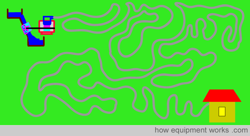
This power station may be many hundred miles / kilometers from your home or hospital and this means that the electricity has to travel very far before reaching you. One big headache for the power company is that when electricity travels in wires, it loses energy. If this happens over huge distances, there will be nothing left when the wire reaches you.
There is a physics principle that wires carrying a low voltage have higher losses than wires carrying an high voltage. (The explanation for this beyond the scope of this website.)
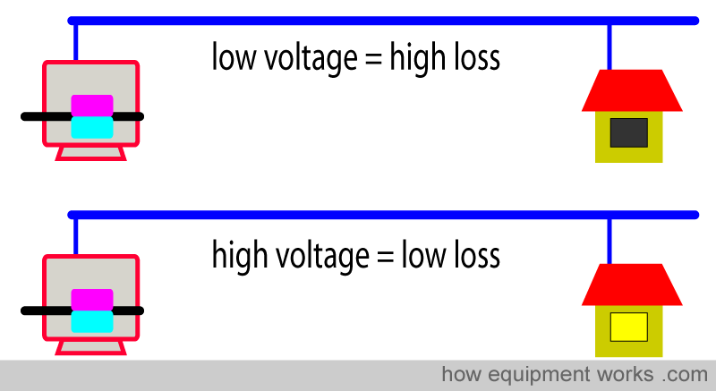
Therefore, to minimise losses, the power company transmits electricity at high voltages.
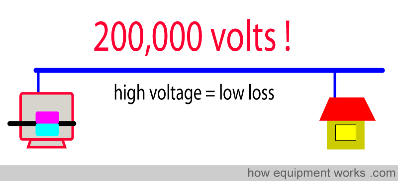
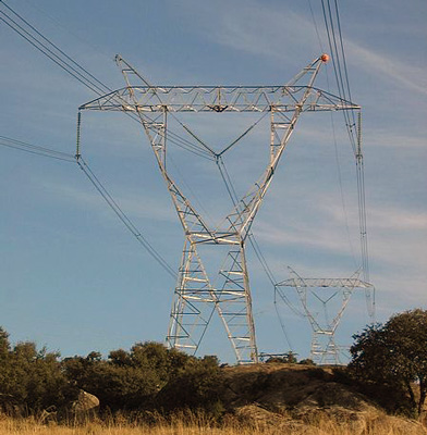
These high voltage power lines can often be seen crisscrossing the landscape. Next time you are outside, do have a look for them.
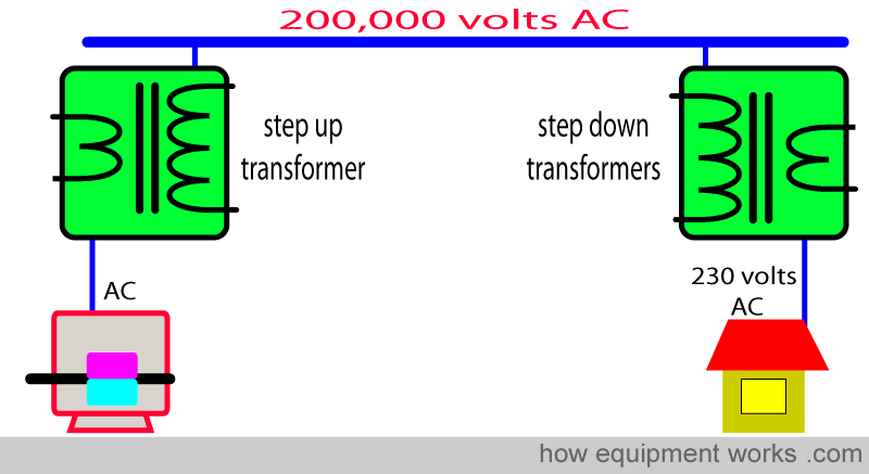
This is where transformers come in. Generators produce a relatively low voltage. This low voltage is raised by a step up transformer to an high voltage, which is used to send the electricity over a long distance. As the wires reach you, the high voltage is reduced using a series of step down transformers. The only practical way to generate the high voltages and subsequent reduction needed for economical power transmission is to use transformers. And that is why AC is used for power transmission, all way to the wall socket in your hospital and home.
Summary:
It is important that you know about electricity. It will help you to better understand electrical safety.
Current is related to the flow of electrons and is measured in Amperes.
Potential difference is what makes the electrons flow (current) and is measured in “Volts”. There are many sources of potential difference such as batteries, electrical supply sockets at home and hospital etc. Current is directly related to the potential difference, and this forms part of Ohms Law.
Resistance is something that resists current flow and is measured in Ohms. Current is inversely proportional to resistance. This relationship forms part of Ohms Law.
Ohms Law defines the relationship between voltage, current, and resistance. If you know two of the three components of Ohms Law, you can find out the third.
Current can be DC or AC. In DC, the electrons flow in one direction whereas in AC, the electrons alternate their direction.
You know (thanks to a oscilloscope) how DC and AC behaves over time. You know how the AC waveform is formed.
Transformers are needed to make high voltages needed to economically send current over long distances. Transformers work only with AC, and that is why the power company supplies your home and hospital with AC.
Now that you have a basic understanding of electricity, you can safely read “Electrical Safety”by clicking on the menu at the top of this page.

Hello! My name is Pras and I am the author of this website that you are now reading. I have made this website completely free to access so that people from all over the world can benefit from it.
If you can afford it, I would be very grateful if you would consider making a single donation of one dollar (or the equivalent in your currency) to help cover the expenses needed to run this website (e.g. for special software and computers). For this website to survive, donations are desperately needed. Sadly, without donations, this website may have to be closed down.
Unfortunately, perhaps because many people think that someone else will donate, this website gets only very few donations. If you are able to, please consider making a single donation equivalent to one dollar. With support from people like you, I am sure that this educational website will continue to survive and grow.


