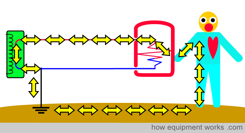
We will discuss the following aspects. Please scroll down and start reading.
- Why is electrical safety important in the operating room?
- The body must be part of a complete circuit to get a shock
- Time for a cup of tea
- Concept of Earth (Ground)
- Basics of Electricity Supply and Neutral Wire
- Basic shock pathway
- Insulation
- How the “wire from equipment case to mother earth” protects you (earth wire)
- Isolation Transformer
- Micro shock
- Safety classifications
- Effects of electric shock
- What can you do for safety?

I would be grateful for a small favour (not money!) that will take you only 5 seconds! Apart from this equipment website, I am interested in the psychology of long-term physical pain, especially how one’s mind can influence the amount of pain one feels. I want to make a free website that explains how to think in ways that reduce one’s pain. For the website, I have purchased the website names listed below, but I’m unsure which one is best. Please vote for the name you think is better. Your answer will help me decide which to use. Thank you!
Important note:
To understand electrical safety, it is crucial that you first understand the basic concepts of electricity. This website has a section dealing with “basic electrical concepts”. If you wish to read that section first, please click on the green battery below. If you already understand the basics of electricity, just continue reading.
Why is electrical safety very important in the operating room?
Like all tools in life, electricity can be your friend or your enemy.
Electrical faults can harm your patient and you. The risk is very real. I know this because some time ago, electricity nearly killed me while I was at work in an operating theatre (not in my current hospital !). A surgical operation was going on and a wiring fault happened in the power plug extension box shown below:

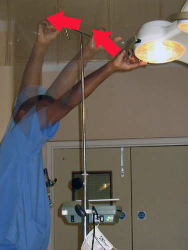
Because of the fault, there was current everywhere including on the IV drip stand below. When I helped to move an operating light, my arm touched the electrified drip stand. An electrical current passed from the IV drip stand to my arm and then went across into the operating light (see arrows). I felt quite a jolt of pain and managed to move my arm away.
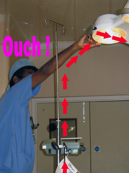
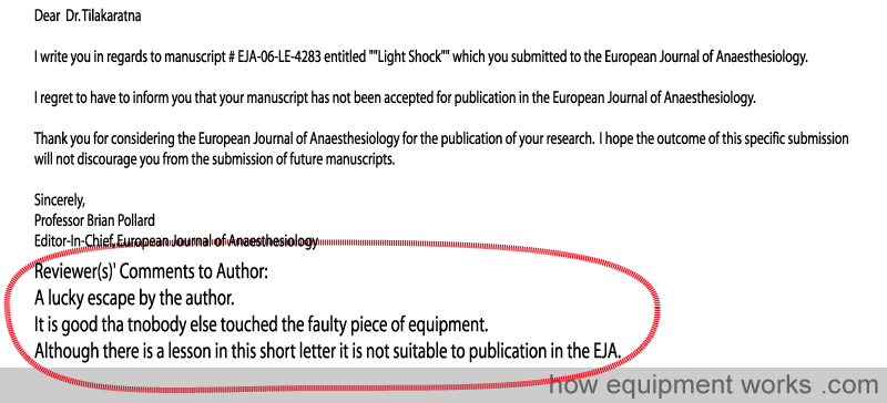
To cut a long story short, I survived the episode (otherwise I suppose I wouldn’t be writing this !). The pictures above were taken soon after the incident. I got someone to take the pictures as I was hoping to publish the incident as a case report or letter in an anaesthesia journal. Unfortunately even having a near-death experience was not enough to get it published! Here is the rejection letter. I do like the bit circled in red …..
Anyway here are some reasons why electricity is particularly dangerous in the operating room.
1. Operating rooms are full of electrical equipment.
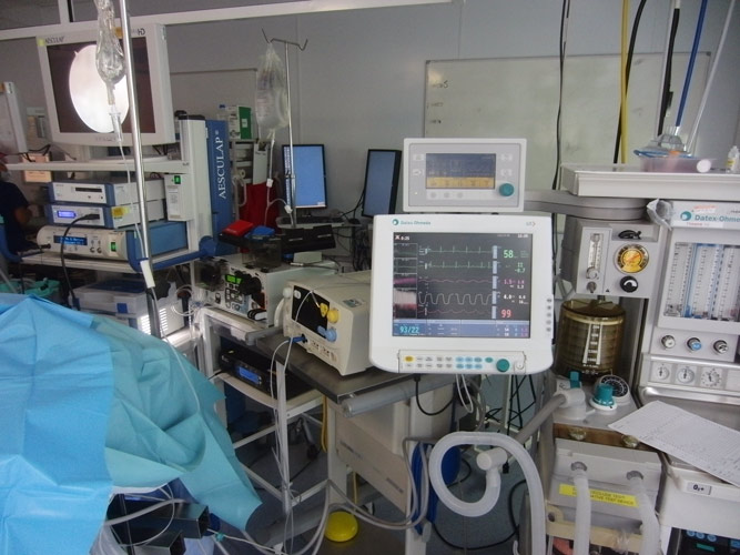
2. Anaesthetised patients are “helpless” and can’t move away from a shock. In the example of me getting an electrical shock, what probably saved me was my ability to quickly move my arm away. Unlike me, who was quite awake, the anaesthetised patient getting an electrical shock could not shout for help or move away, increasing the risk of harm.
3. Electrical current is invisible: Fire, like electricity, can be both useful and dangerous. Fortunately, fire is visible, so you are unlikely to touch it.

Electric current is however more dangerous than fire because you can’t “see” it. Below is a metal spoon.

Now we pass a dangerous electrical current through the same metal spoon.
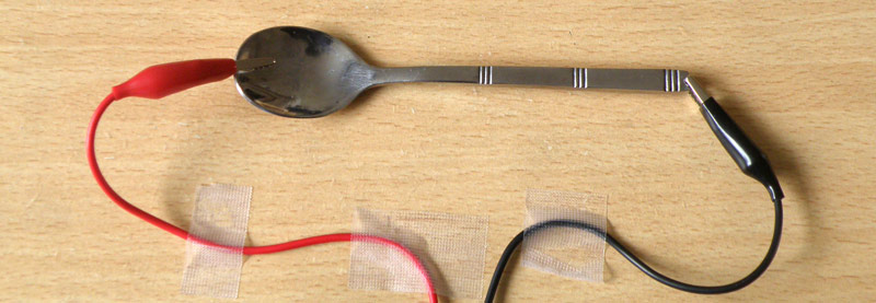
You can see that the metal spoon looks the same with and without current. That is the danger of electricity. It is invisible. If you touched the electrified spoon, you would get a possibly fatal spoonful of electrical shock.
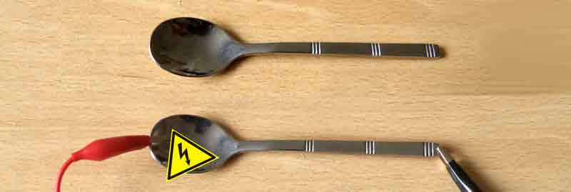
(I know it is obvious, but please do not try the above experiment yourself !)
4. Operating rooms are full of fluids :

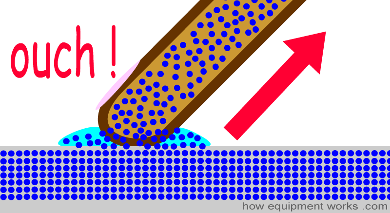
Electrical shocks are more likely to be nasty in the presence of fluids. It has got to do with the fact that wet skin has a much lower resistance to current than dry skin. You have read elsewhere on this website (electrical basics) that current flow is related to resistance. A high resistance makes less current flow while a low resistance makes more current flow.
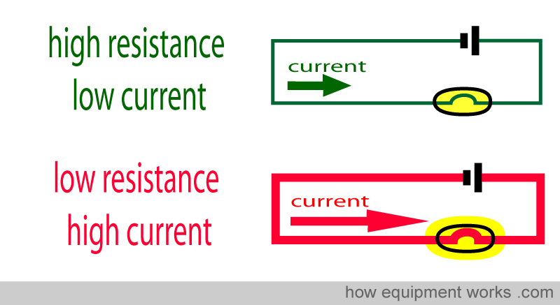
Let us imagine that you touched a metal surface that has an electrical fault with a “dry “ finger.
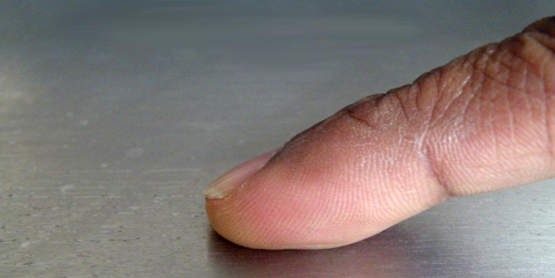
The dry finger has a high resistance. Therefore, only a small amount of current will flow from the metal surface to inside the body.
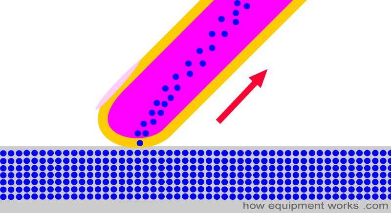
Now imagine that you touched the same metal surface, but this time it was wet with saline or some other fluid.

Generally, liquids have a much lower resistance to current flow than dry skin. Therefore, your wet finger allows a much larger amount of current to flow through you, giving you a big shock.
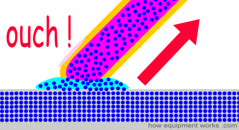
So, wet skin, because it has a low resistance, makes you have a higher risk of harmful electrical shock.
The body must be part of a complete circuit to get a shock
As we go along, we will learn many concepts necessary for understanding how electric shocks happen. Later, we will be able to combine these individual concepts together to explain how electrical shocks happen and the defence mechanism against them.
Let us start by discussing the concept that, in order to get a shock, you must be part of a “completed electrical circuit “.
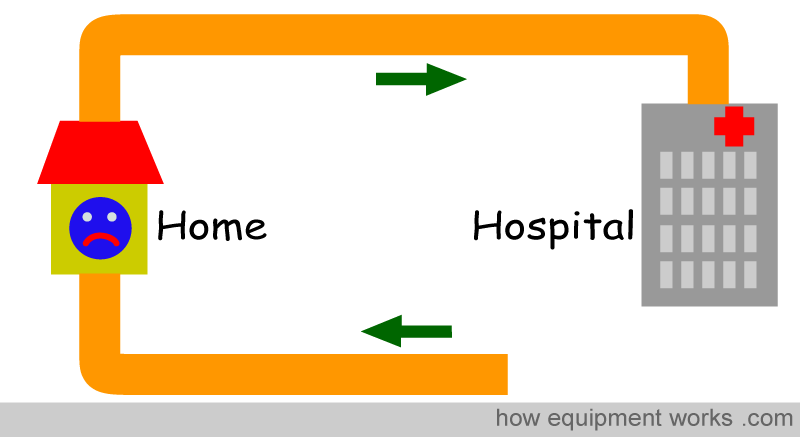
Let me explain. Let us imagine that you live in a nice little house and there is a road that takes you to the hospital and another road that brings you back home.
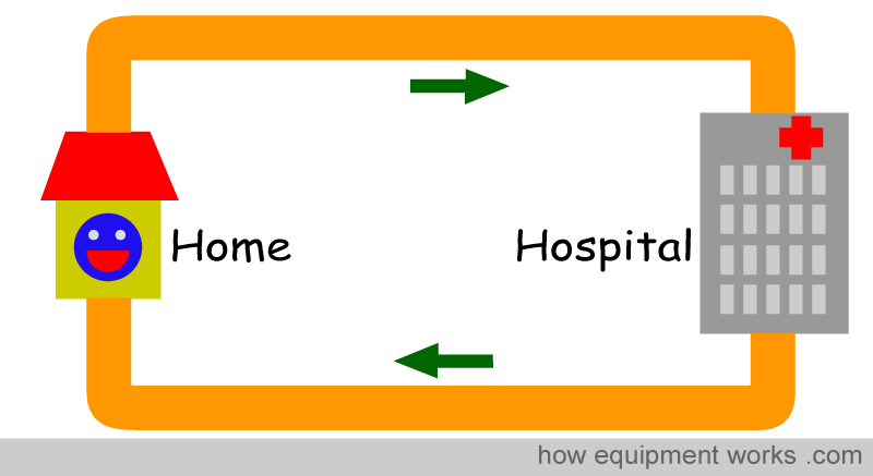
I am sure you are a hardworking person earning some money for your family (okay, just pretend you are a hardworking person …). You leave your home in the morning to work in your hospital.
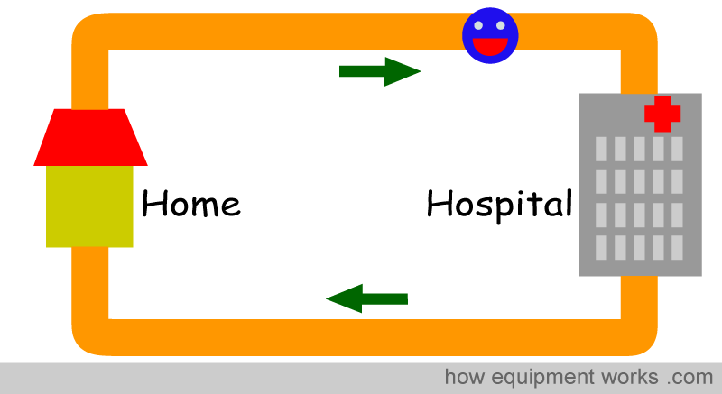
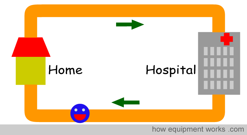
But by the end of the day, I am sure that you eagerly return back to your home.
Now suppose your hospital management suddenly changed the working arrangement. The highly “˜intelligent’ managers in your hospital decide to make a weird new contract where if one worked in the hospital, that person would not be allowed to go home. They do this by removing part of the road leaving the hospital.
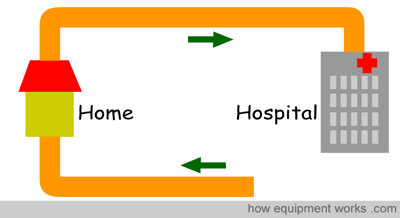
Obviously, with this contract, you decide not to work. The reason is, that if you went to work, you would not have a way to return back home. In other words, because you have no “return pathway”, you don’t even leave home.
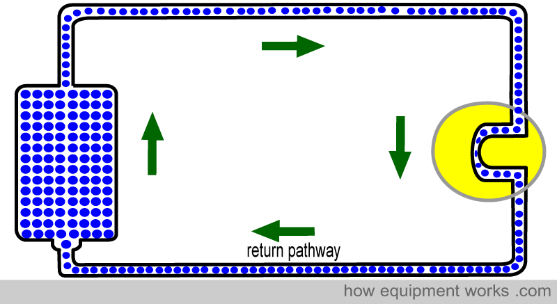
Electrical current is the same. Current likes to do work, but will do so only if it has a “return path” to its “home”. In the example below, current flows from the battery because it, after doing work (lighting up the bulb), is able to return back to the source of the current.
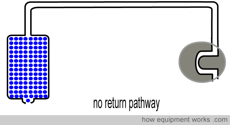
If there is no return pathway back to the source, the current will not flow. (Just like people will not go to work if they have no return pathway to their home.) In the example below, there is a path from the battery to the place of work (light bulb). However, there is no return path back to the battery. Since there is no return pathway, current doesn’t flow through the bulb and the bulb remains unlit.
The same concept applies to electrical shock. Electrical shock is due to the flow of current through the body.
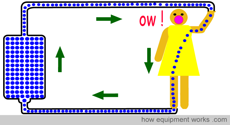
For the shock to happen, there must be a pathway from the source of current to the body and a return pathway back to the source (complete circuit).
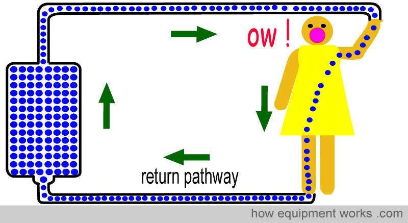
If there is no return pathway, then no current flows and therefore there is no shock.
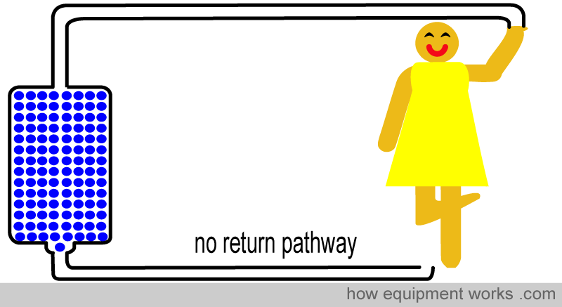
So remember, for electric shock to happen, there has to be a flow of current. For a flow of current to happen, there must be a completed circuit. I.e. the current must have a way of returning to where it came from (source). Do remember this concept. We will return to it later, where it will become useful to understand how electric shocks happen.
Time for a cup of tea
Now it is time to select a piece of simple equipment that we can use as an example in our discussions. I suggest we use an electric kettle as an example. I know that an electric kettle isn’t a common thing to find inside the operating room. Nevertheless, an electrical kettle will serve us well to understand many basic concepts, which you can later apply to other equipment such as an anaesthesia machine. So imagine yourself having a tea break in the staff room and there is an electric kettle there.

I can’t draw a real kettle very well, so please accept my simplified version shown below. Please note that this electric kettle is made of metal (i.e. not plastic).

Inside the kettle is an electric heating wire (shown in red )
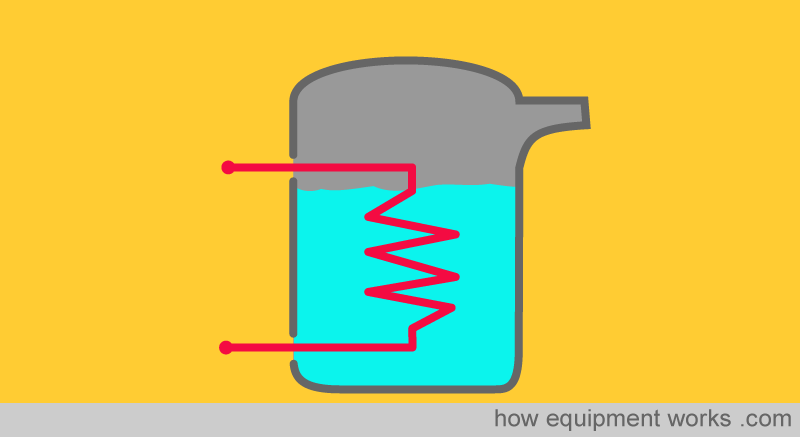
When an electric current (pink arrows) is applied across the heating wire, the wire heats up and boils the water.
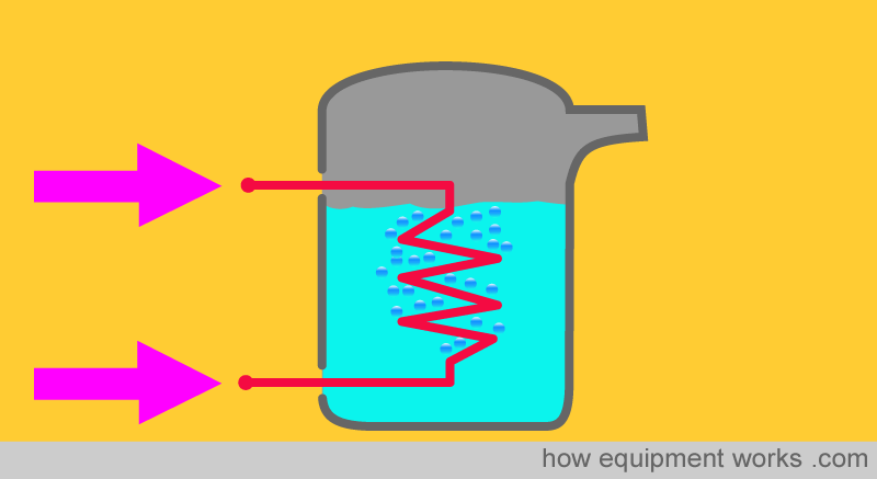
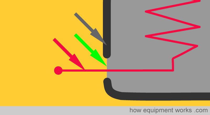
Note that the wires carrying electricity (red arrow) do not touch the metal case of the kettle (grey arrow). There is a gap (green arrow) between them which is there to prevent current from spreading to the metal casing.
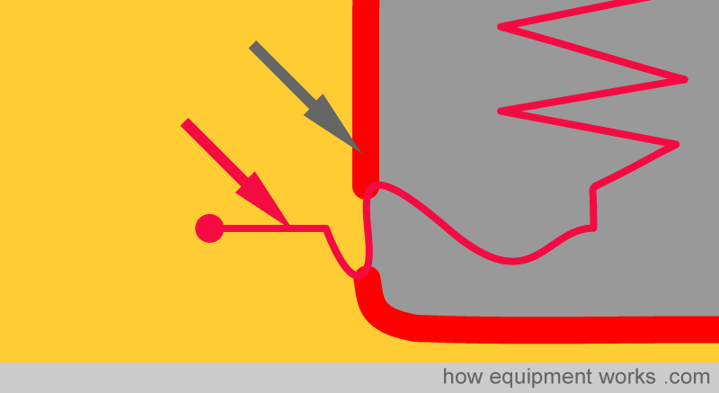
Let us now create a “fault” in this kettle. Imagine that the wires carrying current (red arrow) accidentally touched the metal case (grey arrow). Now, as shown, the metal case would also have an electric current.
If you touched this kettle, you would get a massive electric shock instead of a cup of tea, since the whole case now has ‘current’.
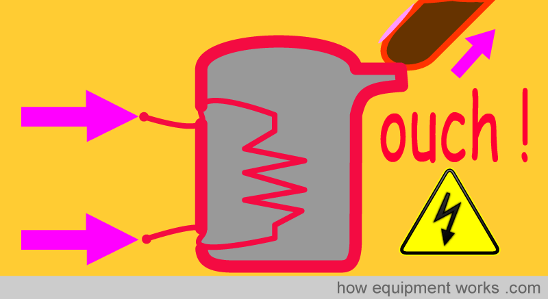
We will return later to this faulty kettle in our discussions. For the moment, let us assume that our kettle has no electrical fault and is safely boiling your water for a tea break.

Concept of Earth (Ground)
We will soon discuss the concept of ‘electrical earth’. However, for a moment, look at the picture below of our planet Earth.

Didn’t see our planet in the above photograph? This amazing photograph shows our planet Earth taken from a huge distance away ( 6,000,000,000 kilometres or 3,700,000,000 miles away !). This photo is a good reminder of the fact that we are so small in the Universe …..

Now let us get back to Earth.
“Earth”, in the context of electricity, is a concept that confuses a lot of people. Unfortunately, it is something you need to understand if you are to understand how electric shocks may happen. Don’t worry, I will clear everything for you.
The main problem I think is that there are many different parts of an electric circuit that refer to the word “earth”. This confuses everyone when one wants to explain things. For example, it is quite difficult to understand this sentence.
“The current goes via the earth wire to earth and then travels in earth and then returns to the neutral wire through an earth wire. “

Let us start clearing up some of the confusion. The first thing is that not all countries use the same name. Some countries, such as the USA use the word “ground” to mean “earth”. So if you are from such a country, please remember that when we say “earth”, we mean “ground” in your country.

Describing Earth:
As mentioned before, the word earth gets used in many places. To avoid confusion, I propose that we use much more descriptive sentences when talking about Earth. We will start by describing “Mother Earth”.
Mother Earth:
One often refers to our planet Earth as “Mother Earth “ since it cares for us like a mother cares for her children. For our discussion, Mother Earth is the surface you are standing on.

From an electrical point of view, one can think of Mother Earth as a huge wire capable of carrying current. Let me explain. Below is an electrical circuit that makes a light bulb light up. From the source, current travels in a wire to the light bulb. From the light bulb, the current returns to the source through another wire.
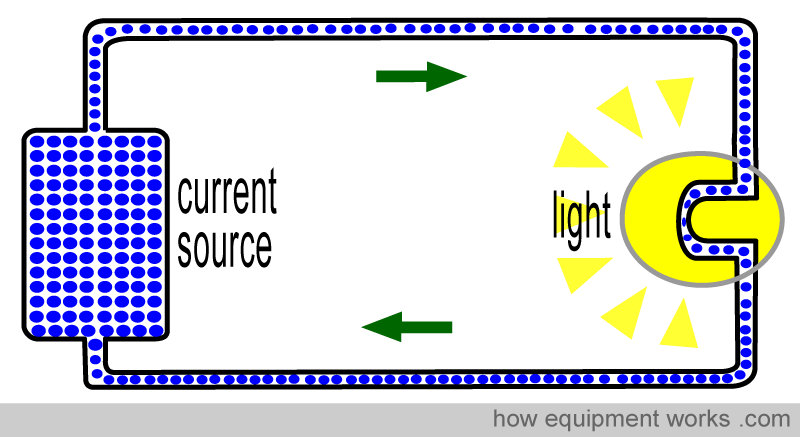
“Mother Earth “ can carry electricity just like a wire can carry electricity. In the circuit below, the wiring arrangement has been altered to allow current to flow through Mother Earth.
The current goes to the light bulb through a wire. However, the current returns to the source through Mother Earth. Note how “Mother Earth” is behaving like a wire.
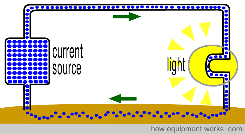
The relevance of the fact that Mother Earth can carry an electric current will become clear when we discuss how shocks can occur.
Basics of Electricity Supply and Neutral Wire
To understand the next sections, we have to have a basic understanding of how electricity is supplied to our homes and hospitals. Do you remember our electric kettle?
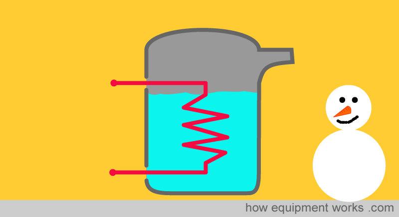
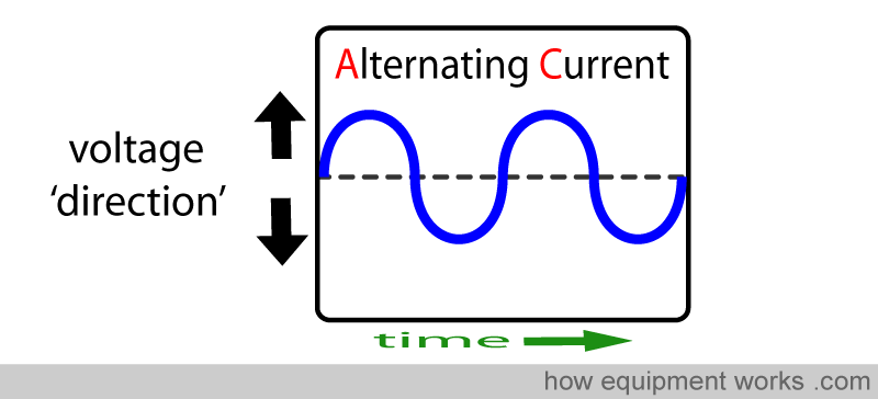
Well, for the kettle to work, it needs an electricity supply. As we saw in the section on basic electricity on this website, house and hospital current is supplied in the form of AC. You will recall that such current changes direction repeatedly.
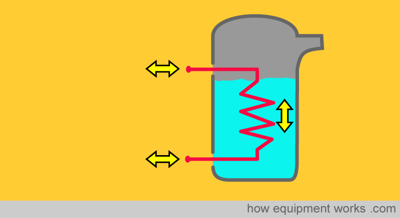
Our electric kettle, like a lot of equipment, needs two current carrying wires to feed it with current. Since it is Alternating Current (AC), the current will be shown as the yellow bidirectional arrows.
In the section on electricity basics, you learnt that the power company, for reasons of efficiency, sends electricity at a high voltage. Near your hospital, it is reduced to a safer voltage by a transformer.
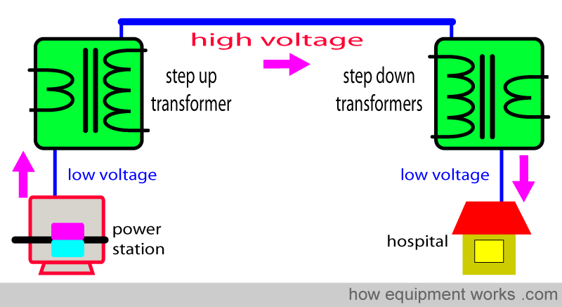
From the step-down transformer, current-carrying wires enter the hospital.
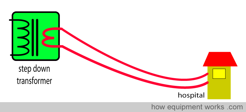
Which ultimately reaches your kettle.
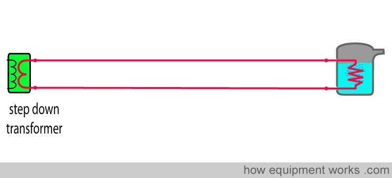
From now on, to keep things simple you will see this simplified kettle ( no more fancy bubbles !).
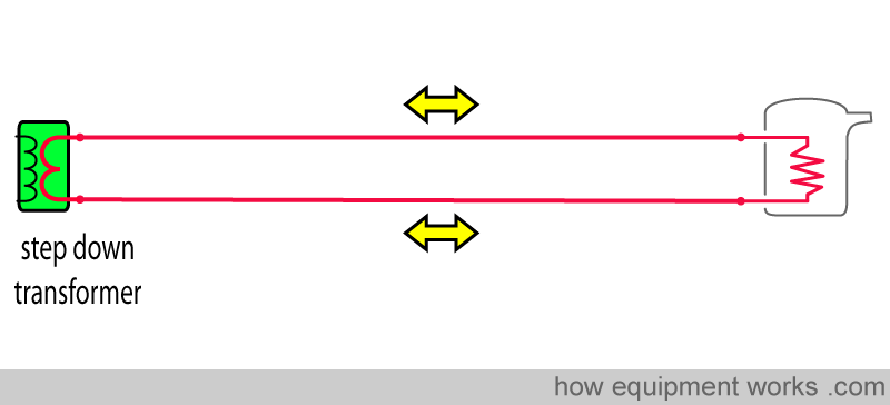
Now we are ready to discuss what I call the “wire from neutral to Mother Earth”. Let us welcome back our beloved Mother Earth into our discussion (please ignore the crazy guy).

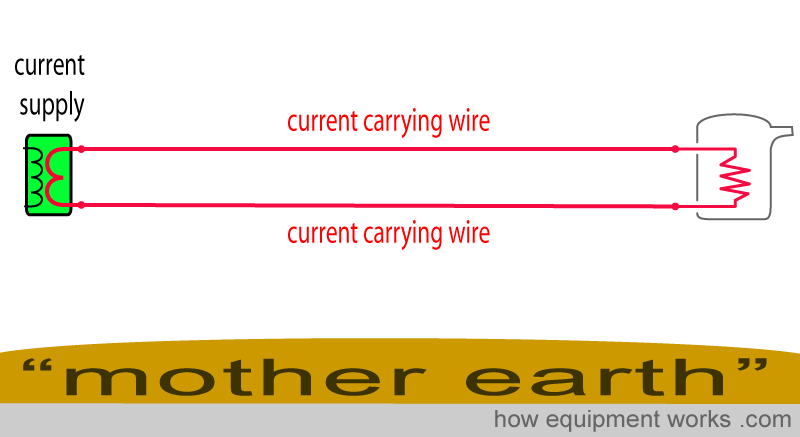
Now here is Mother Earth along with the step-down transformer, current-carrying wires and our kettle.
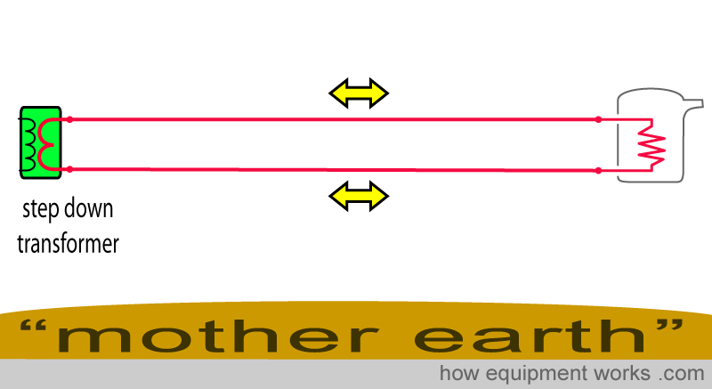
As you have seen so far, there are two wires that supply the electricity to the kettle and so far I have been calling them “current carrying wires”. However, as I will explain later, these two wires will get their own names.
We now find that the electricity supply engineers do something interesting. One of the current-carrying wires is also connected to Mother Earth using a wire (pink arrow).
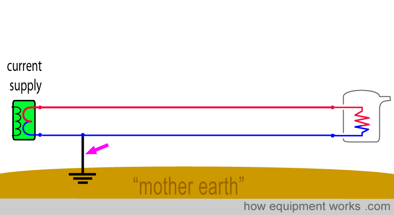
Once this mysterious thing is done, the two current-carrying wires are given their own names. The wire that has a connection to Mother Earth is called the “neutral wire”.
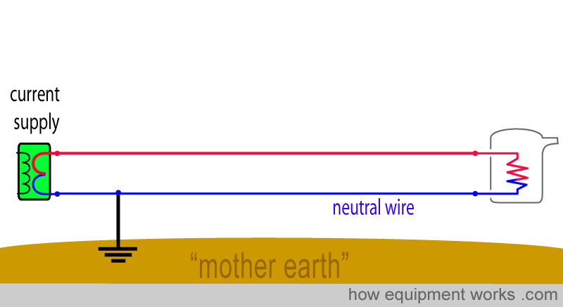
The “other” current-carrying wire, that has no connection to Mother Earth, is called the “live wire”.
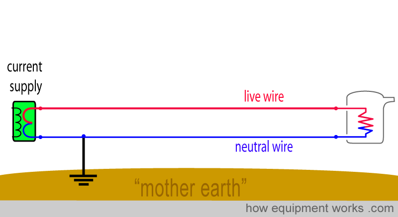
And I will call the wire that connects the neutral wire to Mother Earth…… as ….. “wire from neutral to Mother Earth”!
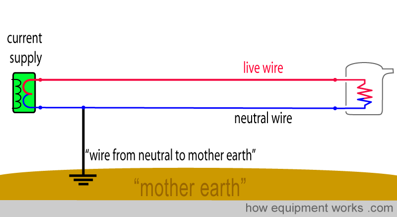
Now the big question is: Why do the electrical engineers connect the neutral wire to Mother Earth?
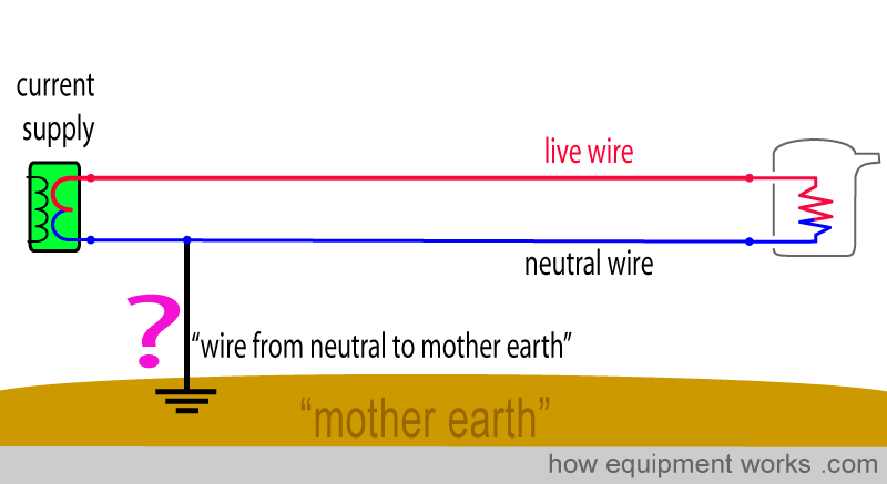
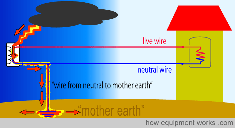
There are highly technical reasons for having the wire from neutral to Mother Earth, the details of which we shouldn’t probably worry too much about. However, one reason for having this arrangement is that the wire from ‘neutral to Mother Earth’ protects us from lightning strikes and I will explain this to you briefly.

The electrical supply system (electrical grid) is mostly outside and exposed to the sky. Therefore, it is quite vulnerable to lightning strikes.
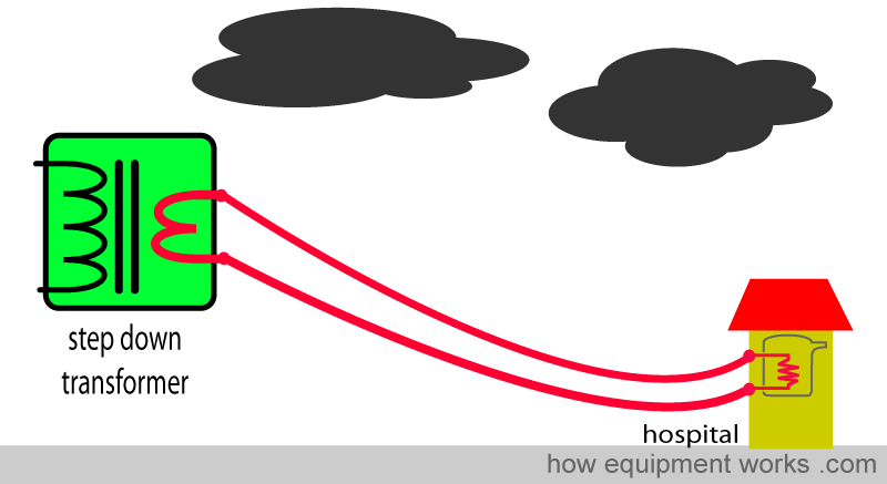
Let us imagine that lightning hits part of the electrical supply.
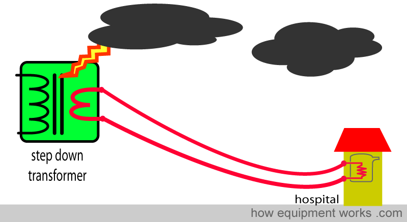
This lightning can result in very high currents that could travel through the wires into your hospital, causing major destruction.
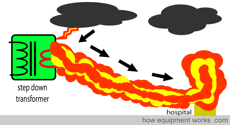
However, thanks to the ‘wire from neutral to Mother Earth’, there is some protection against this. The dangerous current from the lightning strike goes through the neutral wire (see arrows) to the “wire from neutral to Mother Earth”. Then from the wire from neutral to Mother Earth, the current finally goes into Mother Earth. In this way, the lightning current safely goes to Mother Earth instead of going to your home or hospital and causing damage.
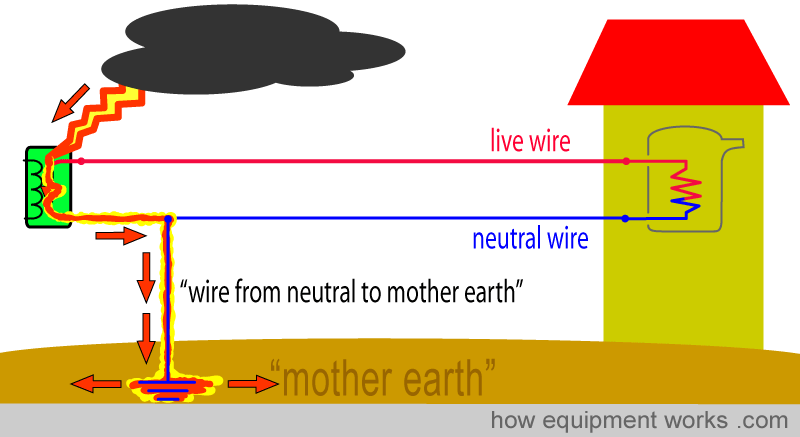
So you see, the neutral to Mother Earth wire is pretty important!
Basic electric shock pathway
We are now ready to see the pathway the current takes during an electric shock. This will help you to understand how electric shocks happen, and more importantly, it will also help you to understand the various methods by which we can be protected from shocks.
Let us bring back our electric kettle. For our discussion, we are going to create a fault. The heating wire is made to touch the metal case of the kettle (pink arrows). This makes the whole metal kettle have electricity. If one touched this kettle, one would get an electric shock.
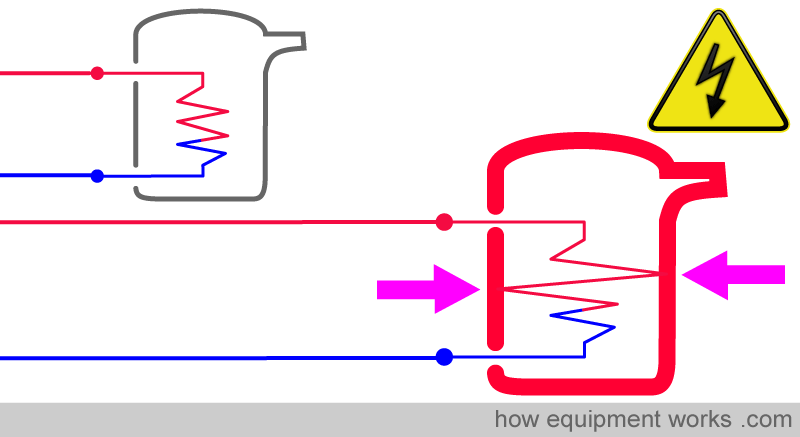
Anyway, right now, our friendly man (shown below) is not touching the faulty kettle and is therefore happy (he won’t be happy for very long). You will recall from a concept that we discussed before, that electric current always wants to return to its home (source). In the diagram below, the current (AC) is shown as yellow arrows. In the image below, the current path is going from the source to the live wire and then to the kettle. From the kettle, the current path returns to the source through the neutral wire. Remember, the current always wants to return home to its source.
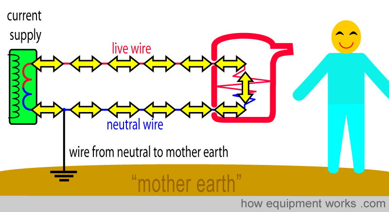
Now finally our man can have his electric shock! Let me talk you through the path the current takes when the faulty electric kettle gives him a shock.
The current starts at the supply part of the power company. This could be a step-down transformer located at a distance from the hospital (1). The current then goes through the live wire (2) and eventually reaches the heating wire of the kettle (3). The kettle has a fault and the heating wire touches the metal wall of the kettle (4) which then becomes full of current. The man touches the metal wall and the current passes into him and travels in his body (5) to his foot. From his foot, the current travels into Mother Earth (6). You will recall from an earlier discussion that Mother Earth can carry electric current like a wire and therefore she carries the electric current from the man’s foot to the “wire from neutral to Mother Earth” (7). The “wire from neutral to mother earth ” carries the current from mother earth to the neutral wire (8). The neutral wire finally carries the current back home to the step-down transformer of the current supply company (1). This sounds like a long description, but in reality, it is fairly straightforward to understand when you see it in a diagrammatic form as shown below.
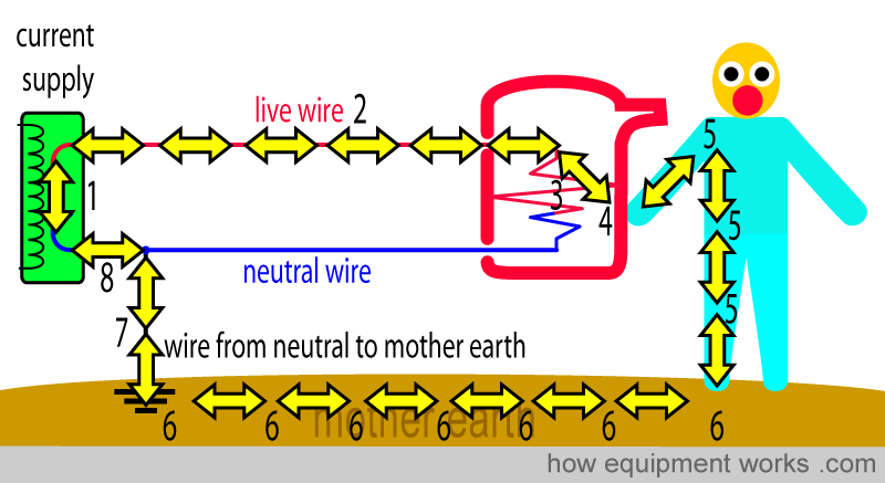
Now that you know the basic shock pathway, we can soon discuss some safety aspects.
Insulation
We learnt earlier that resistance is a measure of how easy it is for current to flow through something.
Something with a low resistance will let a lot of current flow whereas something with a high resistance will allow only a little current to flow.
‘Conductors’ are materials that ‘conduct’ current easily. You will recall that current is the flow of electrons. In good conductors, the electrons are free to move easily leading to easy current flow. Metals are good conductors and are found in wires that carry electricity. Conductors have a LOW resistance to current flow.
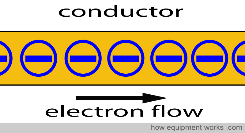
The opposite of a good conductor is an ‘insulator’. Insulators are materials that are very poor at carrying an electric current. Unlike in conductors, in insulators, the electrons are tightly bound and cannot move easily. Because the electrons cannot move, the insulator does not easily carry current. Insulators have a HIGH resistance to current flow.
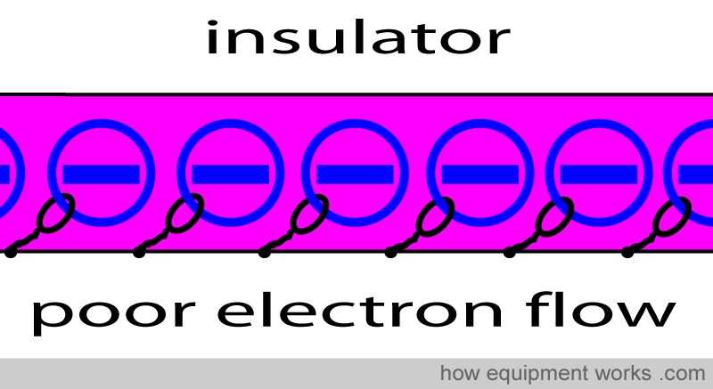
One common application of insulation is to make electric wires safe to use at hospitals and at home. If we simply had metal electrical conducting wires, whenever we touched them we would get a nasty shock.
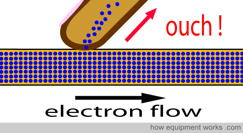
A common solution to the problem is to cover conductors with a layer of insulation. Most wires are insulated in this way. There is a metal conducting portion (red arrows) that has a low resistance to current flow. This is covered by a layer of insulation that has a high resistance to current flow (pink).
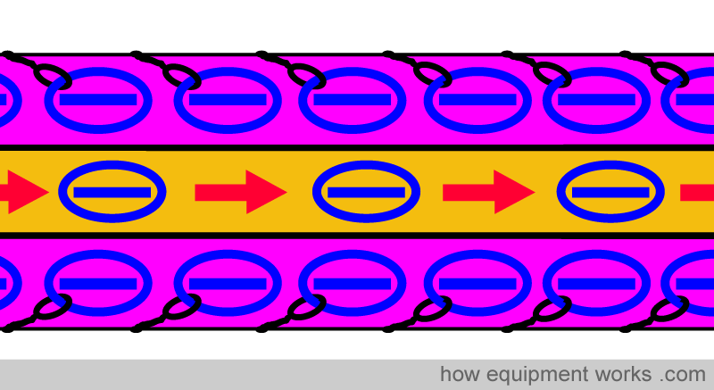
This insulation makes the wire safe to touch.
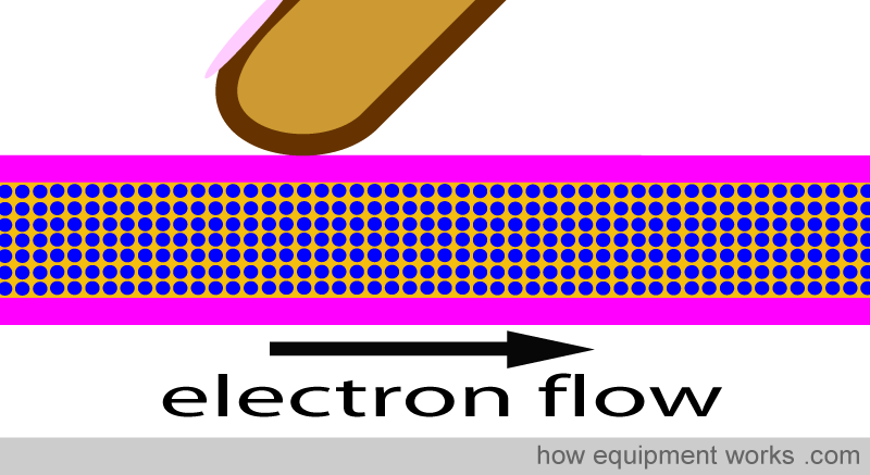
However, one must regularly inspect such wire insulation for damage. For example, in operating rooms, it is not uncommon for a piece of heavy equipment to be rolled over a wire on the floor.
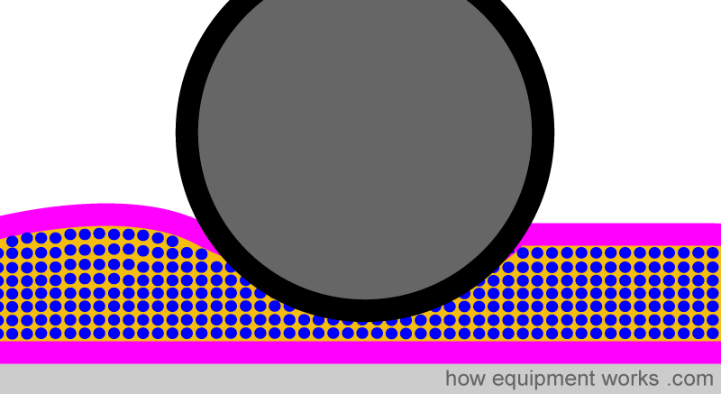
The wheels of such equipment can easily damage the insulation of wires and remove a portion of the insulation.
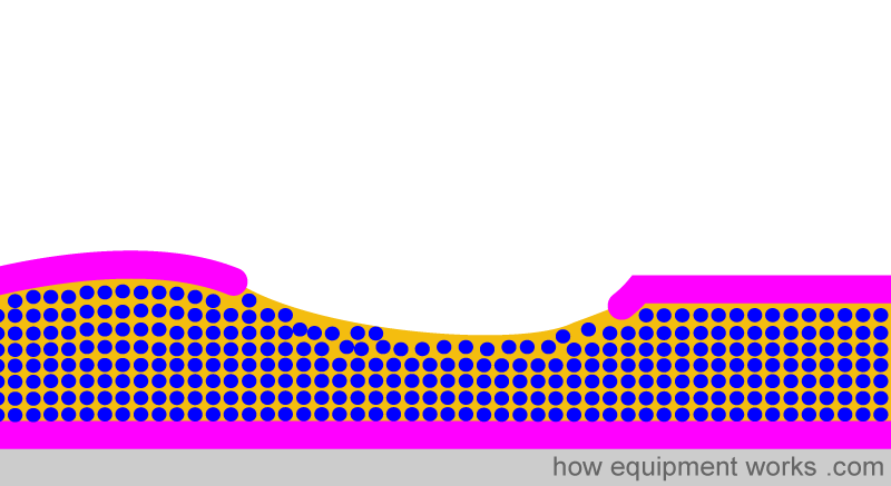
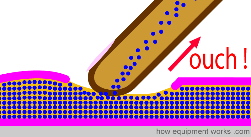
It is now not safe to touch the wire. Since part of the insulation is missing, there is a chance that if you touch this wire, your finger may contact the conductor and get an electric shock. Therefore, always inspect wires that are lying around for damage, taking care not to shock yourself.
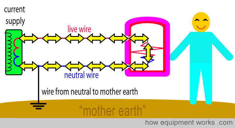
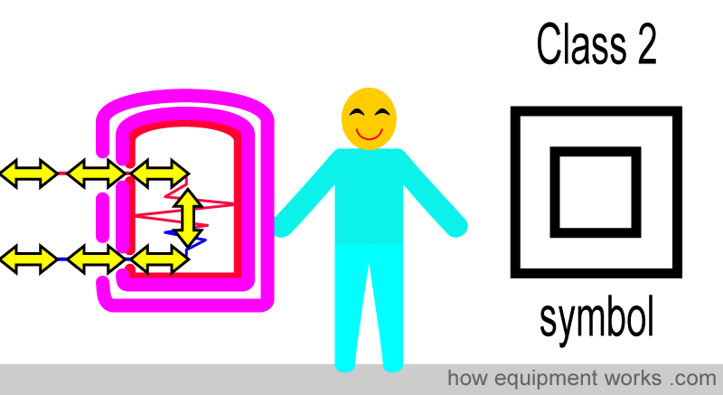
It is possible, as a safety feature, to insulate the surfaces of equipment. When done correctly, all the parts that conduct electricity are covered by a layer of insulation (pink layer). This way, such equipment is safe to touch because the insulation has a high resistance to current flow, and therefore will not cause a shock.
In practice, if equipment relies on insulation for safety, it is protected by at least two layers of insulation (double pink layer). This is called “double insulation”.
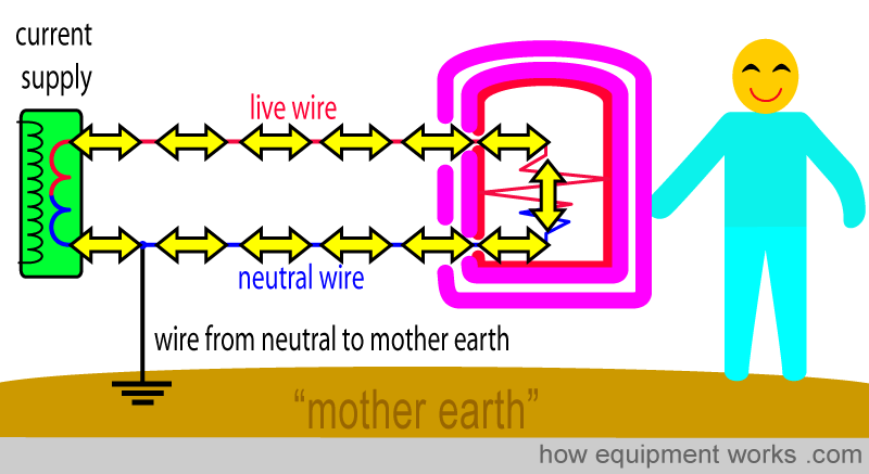
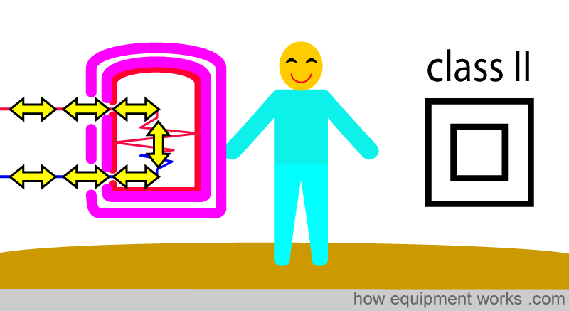
If you look at your equipment, they will often have labels indicating all sorts of things. Depending on local regulations, the symbol below (two square outlines), indicates that the equipment is double insulated. There are various ways of classifying the protection afforded by electrical equipment. Double insulation protected equipment may also be called “Class 2”.
Earlier, we learnt how fluids can lower resistance and worsen shock.
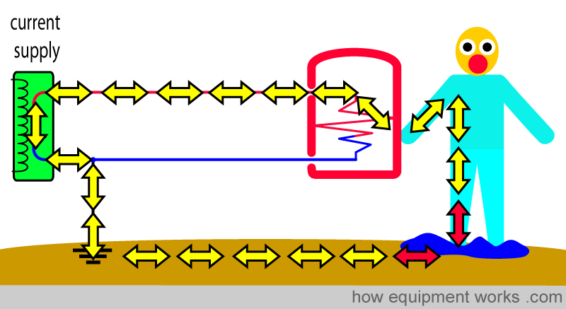
In a similar way, if you are standing on a pool of fluid such as saline, the effect of shock will be much worse. The fluid will lower the resistance between your foot and Mother Earth, making more current flow, and giving you a bigger shock.
We can however do the opposite of this and increase safety. We can increase the resistance by wearing appropriate work shoes that have a high resistance. Such shoes will act as an insulator.
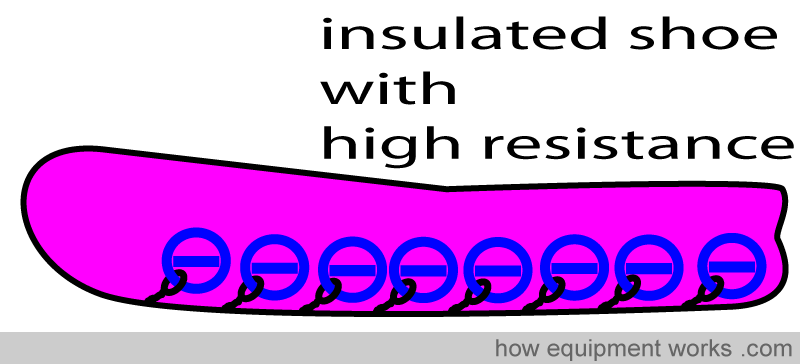
You know that electrical current doesn’t flow through if it can’t get back home through a return pathway. The insulated shoes prevent a return path (small red crosses) from forming and therefore the man doesn’t have a big shock.
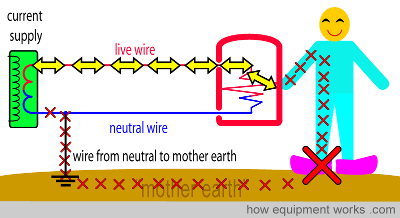
Please wear shoes approved by your hospital. These will have safety features such as having the correct amount of electric insulation and protection from falling sharp objects etc.
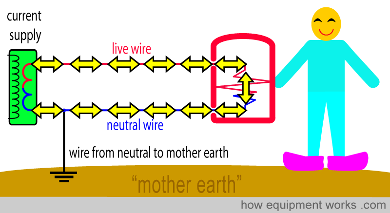

Hello! My name is Pras and I am the author of this website that you are now reading. I have made this website completely free to access so that people from all over the world can benefit from it.
If you can afford it, I would be very grateful if you would consider making a single donation of one dollar (or the equivalent in your currency) to help cover the expenses needed to run this website (e.g. for special software and computers). For this website to survive, donations are desperately needed. Sadly, without donations, this website may have to be closed down.
Unfortunately, perhaps because many people think that someone else will donate, this website gets only very few donations. If you are able to, please consider making a single donation equivalent to one dollar. With support from people like you, I am sure that this educational website will continue to survive and grow.


I would be grateful for a small favour (not money!) that will take you only 5 seconds! Apart from this equipment website, I am interested in the psychology of long-term physical pain, especially how one’s mind can influence the amount of pain one feels. I want to make a free website that explains how to think in ways that reduce one’s pain. For the website, I have purchased the website names listed below, but I’m unsure which one is best. Please vote for the name you think is better. Your answer will help me decide which to use. Thank you!
How the wire from equipment case to Mother Earth protects you
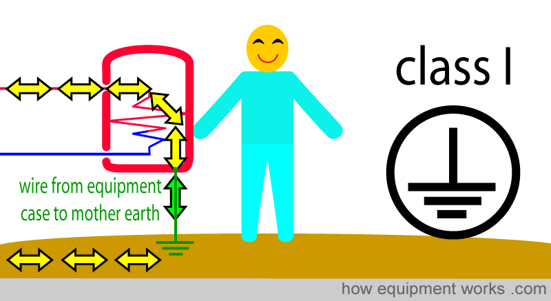
There is an additional wire that we can add to the electrical wiring we have studied so far to make things safer. This is a wire that is used for equipment that has metal surfaces. This wire, which I shall call, “wire from equipment case to mother earth”, as shown below, is connected from the metal casing of our equipment (e.g. electric kettle) to mother earth. This wire I have shown in green below.
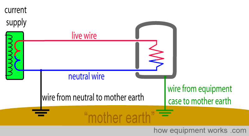
At this point, make sure that you don’t get confused between the two wires that go to Mother Earth.
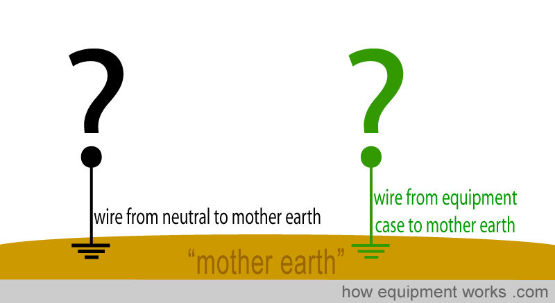
Both the wires go to Mother Earth. However, one connects to the neutral wire (black arrow) and the other connects to the metal case of the equipment (green arrow).
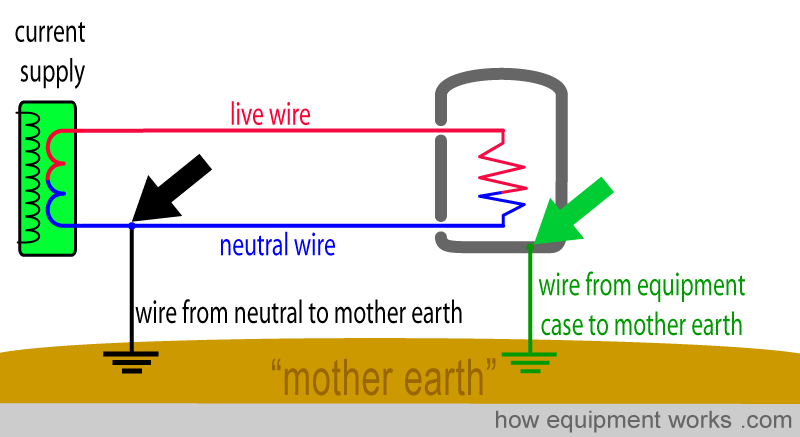
Also, the wire from neutral to Mother Earth is usually some distance from you. On the other hand, the wire from the equipment case to Mother Earth is quite near you, as it is connected to the equipment you are using.
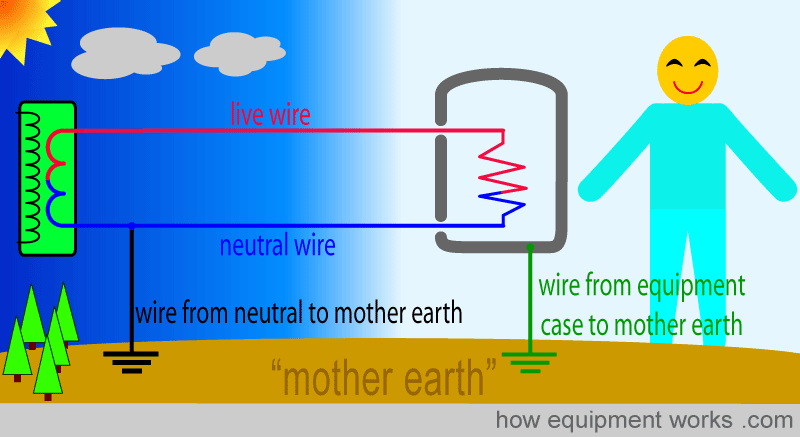
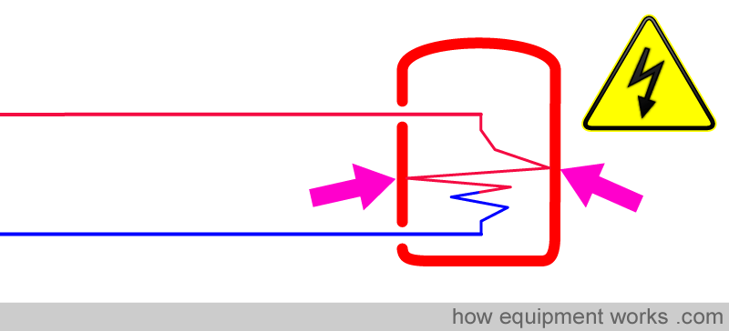
The wire from the equipment case to Mother Earth protects us in two ways as will be explained to you soon. Let us now make our equipment faulty. The current wire inside the device has now touched the case (pink arrows) and the metal case is now full of current. If you touched it, you would get a shock.
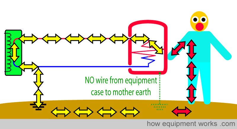
First, let us assume that there is no wire from the equipment case to Mother Earth. As we have discussed before, the current chooses to go through the man, giving him a shock.
Now let us take the same scenario, but this time we have the wire from the equipment case to Mother Earth connected. Now the current has a choice of two paths to take to reach Mother Earth. It can either go through the man (red arrows) or go through the wire from the equipment case to Mother Earth (green arrows).
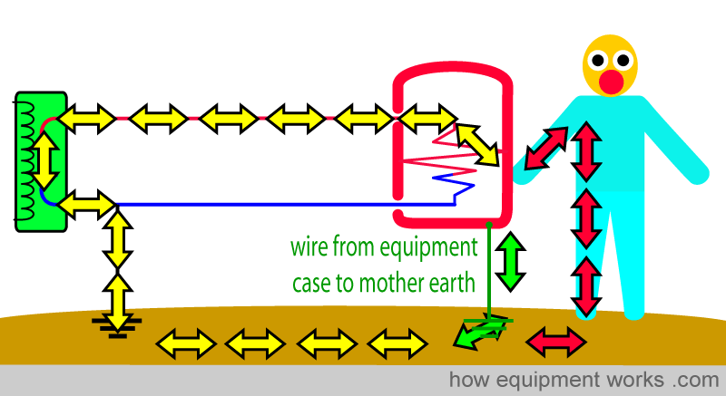
So which path will the current take? One thing about electric current is that like humans, it will try and take the easiest path. As a human, if there are two paths to the same destination, I am sure you will take the one that involves the least effort (blue road below).

Current also likes to take the easiest path. For current, the easiest path is the path with the least resistance. The current has to “decide “ if the man or the wire from the equipment case to Mother Earth has the lower resistance.
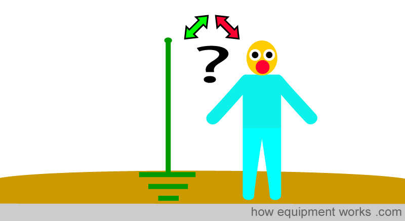
Now which of the two paths has the lower resistance? Wires are extremely good conductors of electricity and therefore carry current easily. Hence, the wire from the equipment case to Mother Earth has the lowest resistance. Humans, especially with their “dry skin “ are relatively poor conductors and have a high resistance.
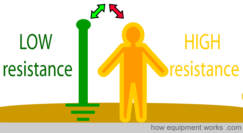
Since the equipment case to Mother Earth wire has a much lower resistance to current flow than the man, the shock current goes through the wire, instead of the man. In this way, by providing an easier path for the current, the equipment case to Mother Earth wire “diverts “ the shock current away from the man.
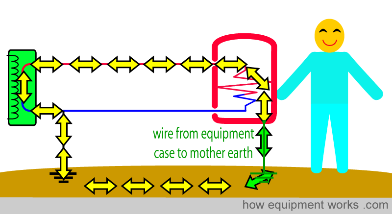
However, this is not the only way the ‘wire from equipment case to mother earth’ prevents shock. Not only does it divert the shock current, it also stops its flow. However, it cannot stop the current flow on its own. Instead, it needs the help of another category of safety devices which for now I will call “high current stopping “ devices. These devices are designed to stop the flow of current when the current through them exceeds a set safe amount. I will first explain what these devices are and then explain how they work along with the ‘wire from equipment case to mother earth’ to stop the flow of current.
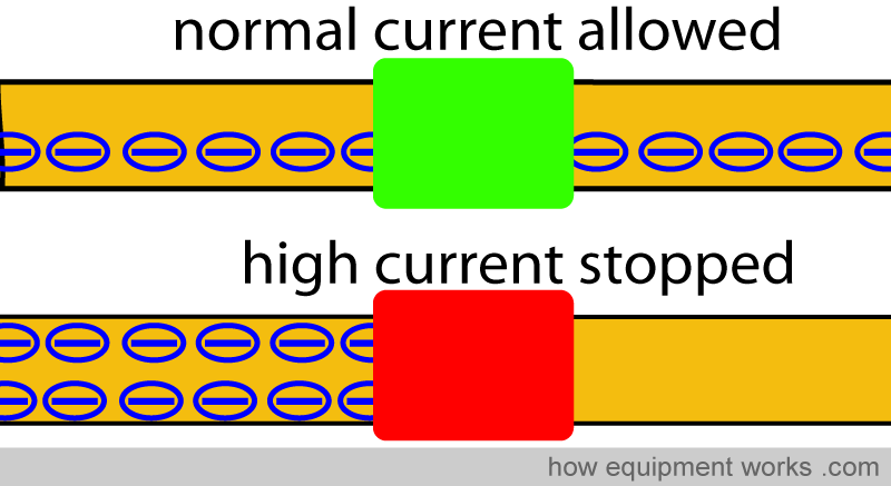
There are two main types of “high current stopping “ devices:
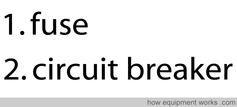
Fuses:
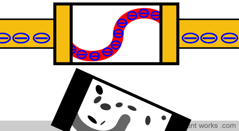
These devices consist of a short length of wire that can easily melt. This wire (red, below) is usually enclosed in a protective cover. The current flows through the device.
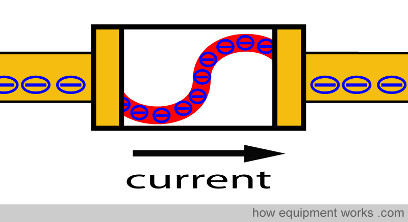
If there is an excessively high current, the wire inside the fuse heats up and melts. The melted wire in the fuse can no longer carry current, thereby stopping the high current flow.
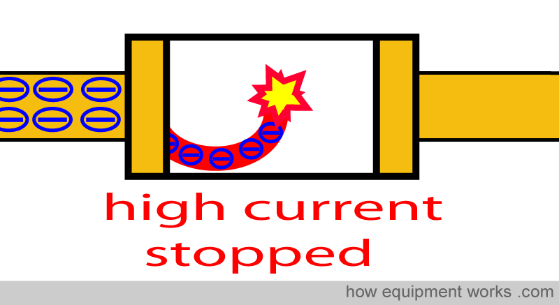
Once the fault that caused the problem is rectified, a new fuse must be installed. I.e. these are “single-use” devices. Fuses are not very expensive to buy, but replacing them is not that convenient.
Circuit breakers:
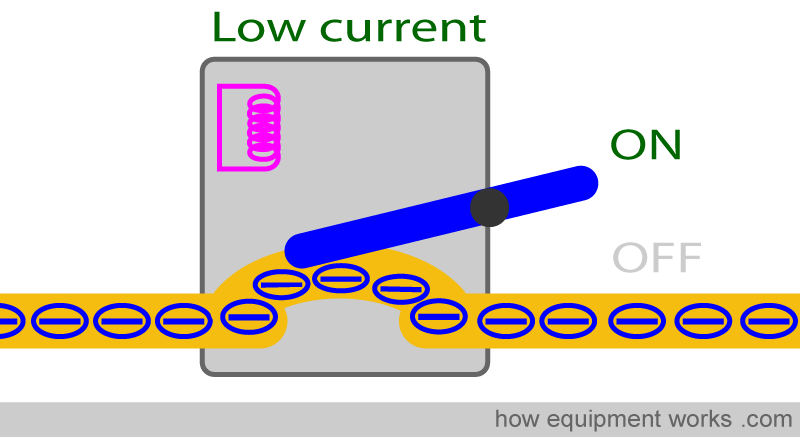
These are more convenient than fuses since they don’t have to be replaced each time they function. Like a fuse, the circuit breaker “breaks “ (stops) the current flow if the current flow exceeds a set limit.
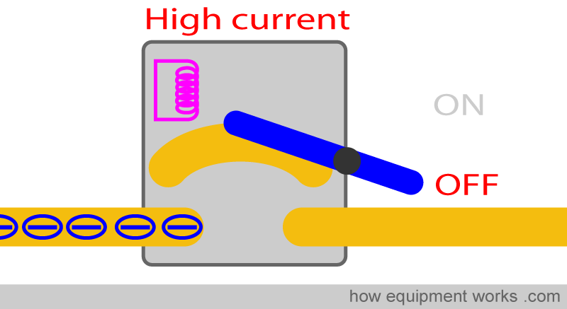
Once the high current problem is solved, the switch can easily be pushed into the ON position and the current will flow again. Therefore, unlike a fuse, nothing needs to be replaced.
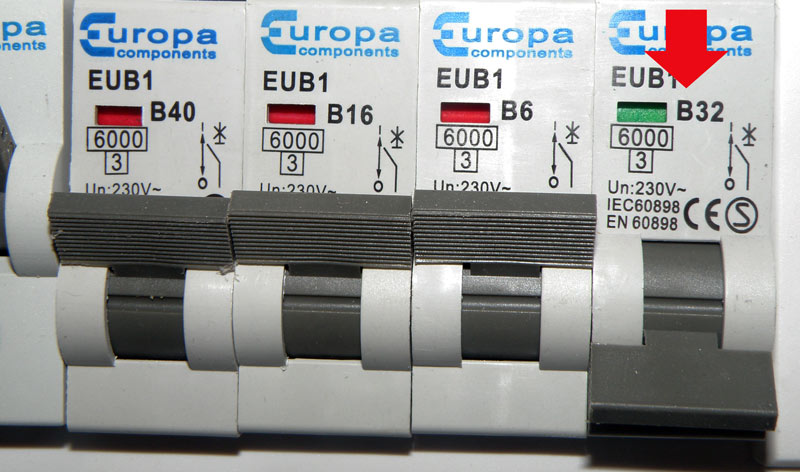
Circuit breakers are also called “trip switches “ . Have a look at your home today. You may have a fuses or circuit breakers. Below is a picture of the circuit breakers in my house. The one with the red arrow has “tripped” into the off position.
These “high current stopping “ devices work together “as a team” with the “wire from the equipment case to Mother Earth”. Let me explain.
Under normal conditions without a fault, a normal current is going to the equipment. The current goes through the circuit breaker which, because the current is not high, remains in the ON position.
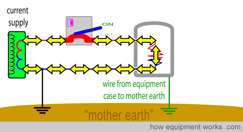
Now let us create an electrical fault.
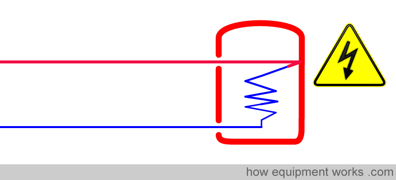
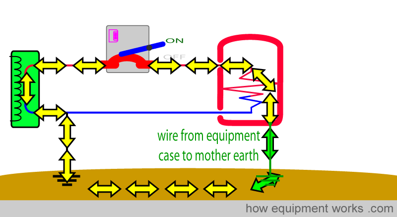
The shock current goes to the equipment case and then goes to Mother Earth. This pathway has a very low resistance and therefore current can flow very easily. This leads to a very large current passing through the circuit breaker.
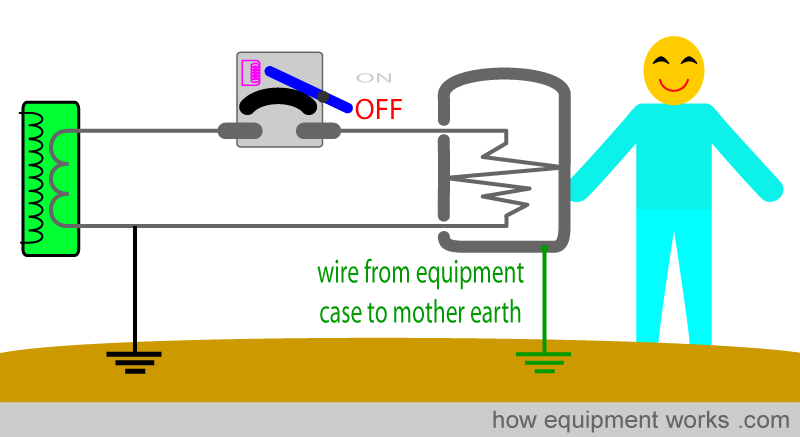
The high current makes the circuit breaker move into the OFF position and stops further current flow. Everything is now safe.
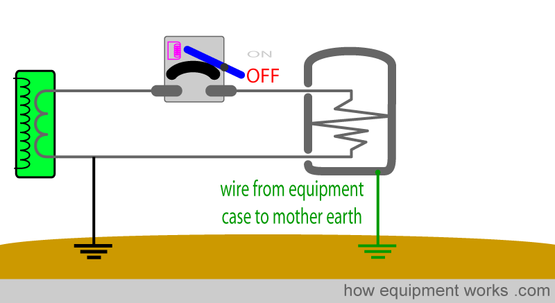
I would like you to note that the wire from the equipment casing to Mother Earth helps in two ways.
Firstly, it diverts the current away from the man.
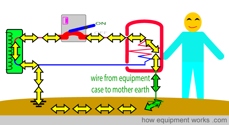
Secondly, it makes a large current go through the circuit breaker which then makes it switch OFF.
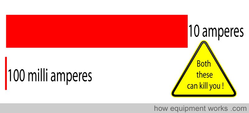
The above system protects you from only relatively large currents, such as 10 amperes. Unfortunately, currents that are much smaller than this, such as 100 milliamperes ( 100 times smaller than 10 amperes) can cause fatal ventricular fibrillation.
Therefore something that is more sensitive than fuses or circuit breakers is needed to protect you. I will now discuss one such device, which for now I will call an “unequal current stopper “. This can stop even small shock currents (e.g. less than 30 milli amperes).
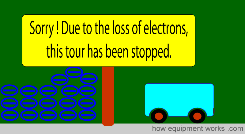
The “unequal current stopper “ works on the principle that what goes out must come back. Let me explain. Imagine that you are running a bus tour for tourists. You send six precious tourists (who have paid you a lot of money) on a tour.

The six tourists go on a long tour enjoying various sites.

And while you are thrilled to see them return, you discover that there is a big problem. Now there are only four tourists, instead of six!

So what has happened? Clearly, you have lost two tourists. You don’t know where it has happened. All you know is that two are missing and must have fallen off somewhere.
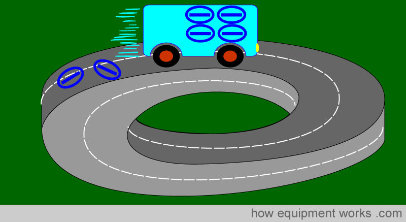
Now there are new tourists waiting to get into your bus for a tour. You of course stop any more tourists going because you know something is wrong. You don’t know where the missing tourists have gone, but you do know that they are getting lost somewhere. You know this because the number of tourists who return is less than the number who were there at the start of the tour. Since this is an unsafe situation and you are an honest tour operator, you shut down your tour service.
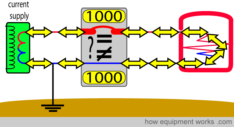
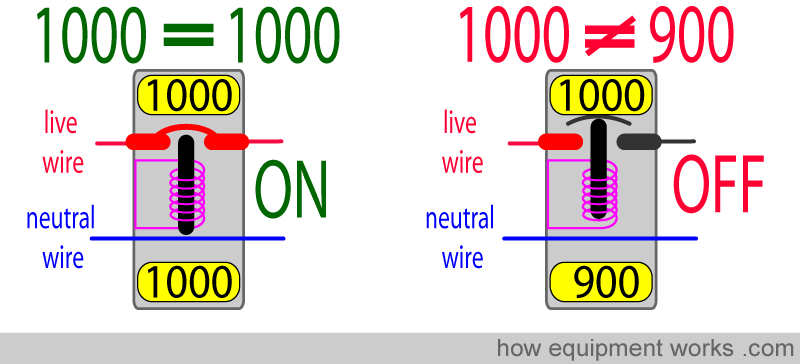
The “unequal current stopper “ works the same way. It continuously checks to see if the amount of current that goes to the equipment equals the amount of current that returns from the equipment. I.e. it compares the current flowing in the live wire and the current flowing in the neutral wire to see if they are equal. In the example below, 1000 milliamperes (1000 milliamperes = 1 ampere) are going to the equipment and 1000 milliamperes are returning from the equipment. Since the current in the live wire equals the current in the neutral wire, the unequal current stopper device remains ON and lets the current flow.
If there is a difference (i.e. it is not equal), as shown on the right below, it switches OFF and stops the current flow.
Now let us see how it can protect against an electric shock. Our man decides to touch the faulty equipment and is getting a shock. The shock current (30 milliamperes in the example below) goes through the man to Mother Earth and returns to the current supply WITHOUT going past the unequal current stopper (see red arrows). Therefore in the example below, while 1000 milliamperes is going through the unequal current stopper to the equipment, only 970 milliamperes returns back through it.
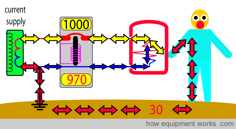
The current stopper detects the unequal current and immediately stops the current supply, making everything safe.
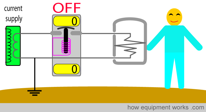
The unequal current stopper is capable of measuring very small differences (e.g. 30 milliamperes) and thus is able to offer good protection against even small but potentially lethal currents.
The “unequal current stopper “ is a name that I made up to make things easier to understand. In reality, depending on which country you are in, this device may be called: “Residual Current Device (RCD) “, “Residual Current Circuit Breaker “, “Ground Fault Circuit Interrupter (GFCI) “, “Ground Fault Interrupter (GFI) “, “Appliance Leakage Current or Interrupter (ALCI). “
Class 1 symbol:
At this point, let me introduce you to another electrical symbol that you may see. Electrical systems that use the equipment case to mother earth wire for protection are called “Class 1” equipment. You may see the symbol below in class 1 equipment.

Isolation transformer
Look at the shock pathway, which you are now very familiar with. You will recall that the shock current returns to the source through the wire from neutral to Mother Earth.
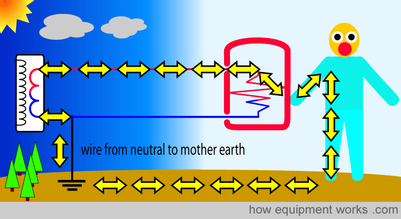
Let us for a moment imagine that there is no such thing as a “wire from neutral to Mother Earth”. Now, in the example below, even though the man is touching the faulty equipment, there is no way for the current to return back through him to the source. Because it can’t return home through the man, it doesn’t even enter him. Therefore he remains happily shock-free.
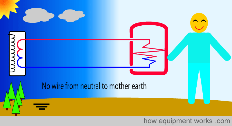
So if the electric company didn’t have a wire from neutral to Mother Earth, we would all be shock-free! But in reality, that is not possible. You will remember that the step-down transformer supplying current is susceptible to lightning strikes.
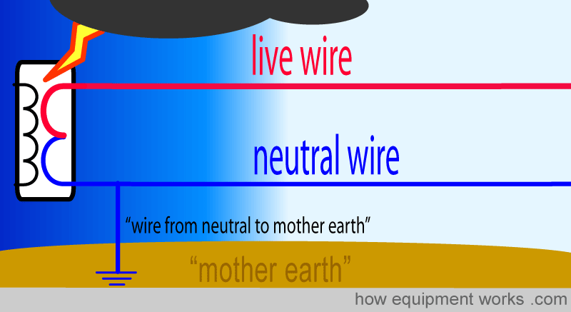
You will recall that the wire from neutral to Mother Earth is what diverts the dangerous lightning current safely to Mother Earth. Unfortunately, we therefore cannot get rid of the wire from neutral to Mother Earth.
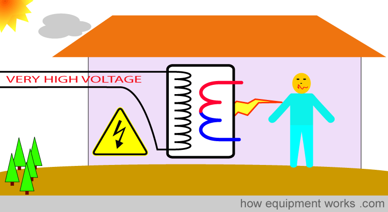
However, there is a trick we can do to get rid of the wire from neutral to Mother Earth. We just discussed how, because the step-down transformer is outside, it is susceptible to lightning strikes and that is why we need the wire from neutral to Mother Earth. But what if we can have a transformer inside our hospital where it will be safe from such lightning strikes? Then we won’t need the wire from neutral to Mother Earth, and everyone will be happy! Unfortunately, that would not be advisable. The step-down transformer works with very high voltages which would present a hazard to those working inside the building.
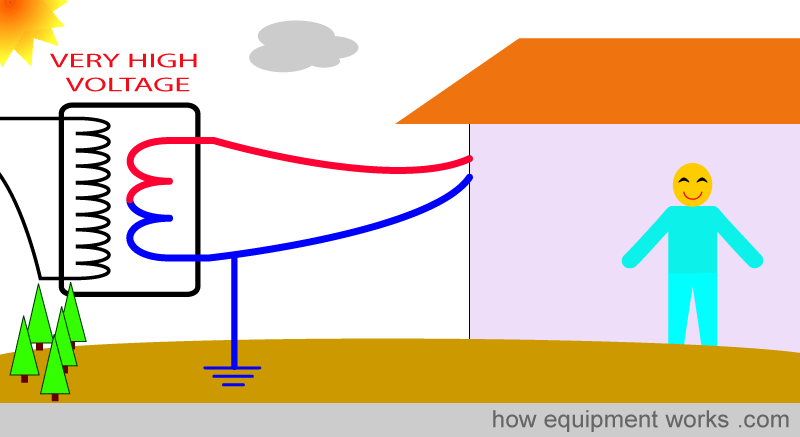
So we move the step-down transformer back again to the outside, along with its wire from neutral to Mother Earth.
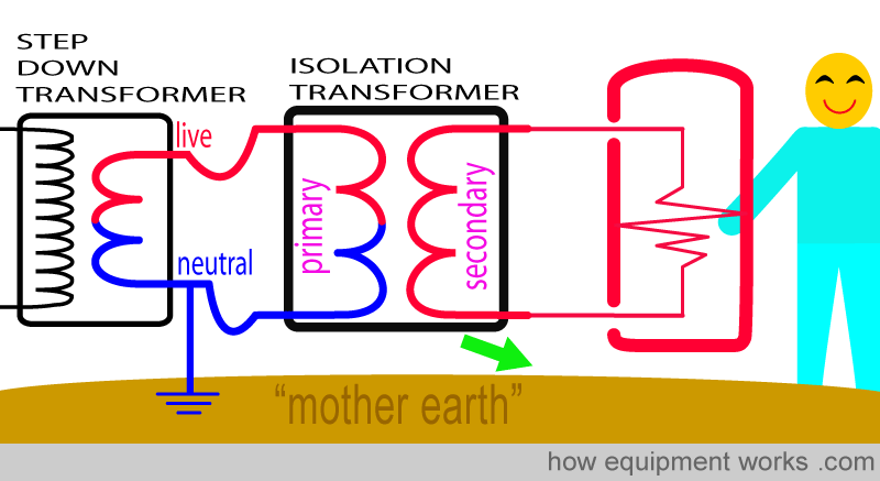
The solution to the problem is to install another transformer. However, before we proceed further, I need to remind you about how transformers work. Transformers are devices that can change the voltage of an AC current (more details were explained to you in the basic electricity section of this website). It consists of two coils. The coils consist of turns of wire. Current enters the transformer and goes to the “primary” coil. The current leaves the transformer from the “secondary” coil.
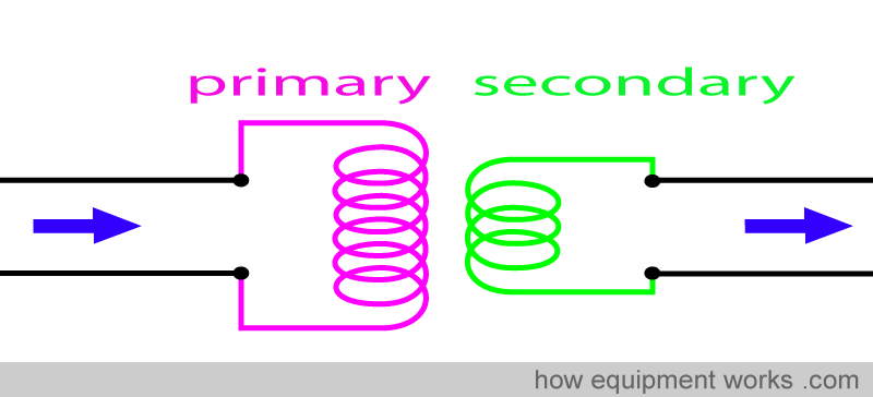
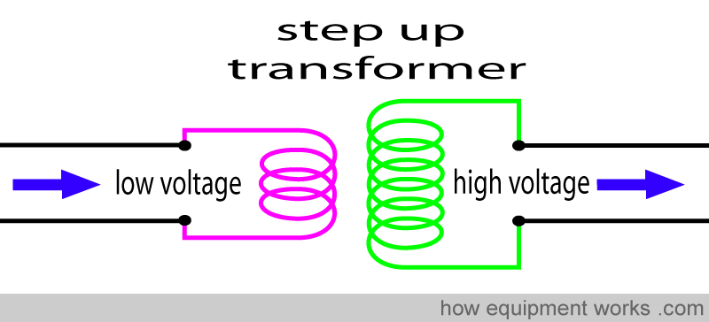
The ratio of the number of turns of wire on either side determines if the transformer raises or lowers the voltage. If the primary coil has fewer turns than the secondary coil, the transformer is called a step-up transformer. This type of transformer raises the voltage.
If the primary coil has more turns than the secondary coil, it is called a step-down transformer. Such a transformer reduces the voltage.
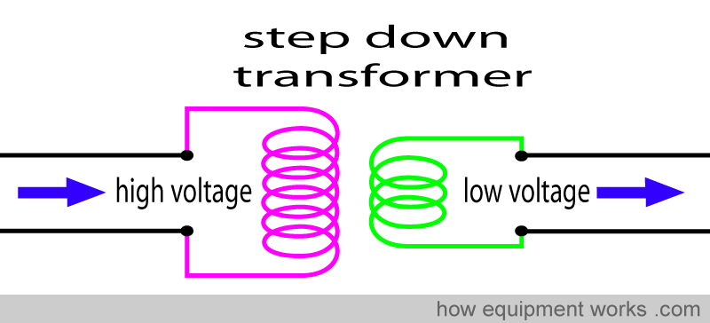
This type of transformer is often found outside your hospital. It reduces the high voltage used for long-distance power transmission to a lower safer voltage that is fed into your hospital.
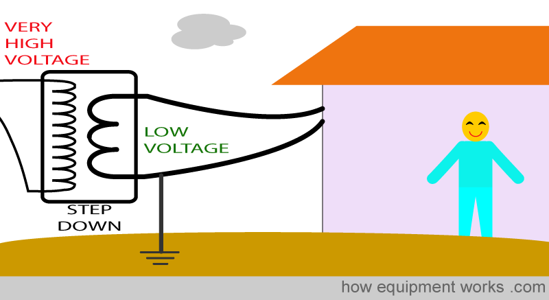
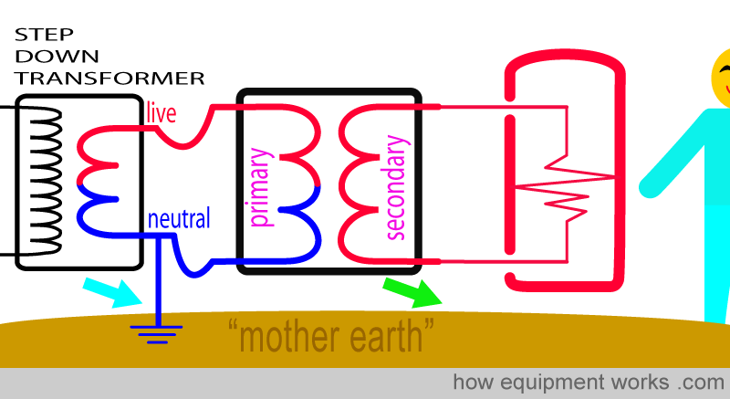
Now let us get back to trying to get rid of the wire from neutral to Mother Earth. For safety, as discussed before, we let the power company keep its step-down transformer well away from us. We also let them keep their wire from neutral to Mother Earth connected.
Now here is our solution. We install another transformer! This one, we safely keep inside our hospital. Because it is not exposed to lightning, it doesn’t have the problems of the transformer outside.
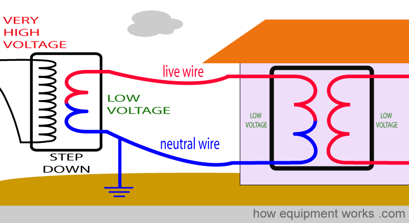
As you have seen, the step-down transformer outside has a wire from neutral to Mother Earth for safety (blue arrow). On the other hand, the second transformer we install is safely inside our hospital and therefore we do not need a ‘wire to Mother Earth’ for this transformer. (wire “absence” shown by green arrow) .
Look at the second transformer that we have inside our hospital. Note that there is a gap ( green arrow) between the coils. Therefore, there is no direct electrical connection between the two sides.
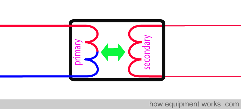
This gap prevents unwanted currents such as those due to shocks from going from one side to the other. In other words, this transformer “isolates” the circuit on one side (blue area) from the circuit on the other side (green area). Because of this, one can call this an “isolation transformer”.

Now let us see how the isolation transformer protects us from shock. You will recall that without such a transformer, the shock current goes through the man and returns to the source by going through Mother Earth and the ‘wire from neutral to Mother Earth’.
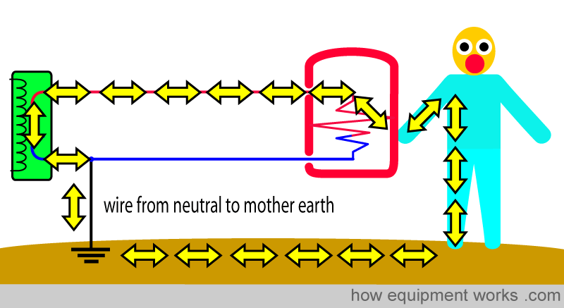
Now let us have our faulty equipment connected to the isolation transformer. The case of the equipment is live with current and our man is touching it. However, he does not get a shock! This is because the current has no way of returning to the isolation transformer as there is no wire from neutral to Mother Earth (wire “absence” shown by green arrow).
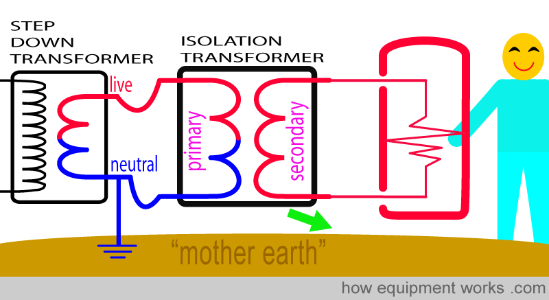
You may wonder why the shock current couldn’t have returned through the ‘wire from neutral to mother earth’ of the step-down transformer (blue arrow). The reason this doesn’t happen is because the isolation transformer has divided the circuit into separate parts. The circuit in the pink part has no direct connection to the circuits in the “non-pink” parts. Shock current cannot travel from the pink part to the non-pink part.
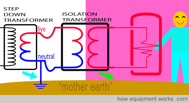
Let me try and make things more clear. For our man to get an electric shock, the current has to be able to return to its source (isolation transformer with yellow triangle). This cannot happen because the isolation transformer does not have a wire from neutral to Mother Earth (green arrow).
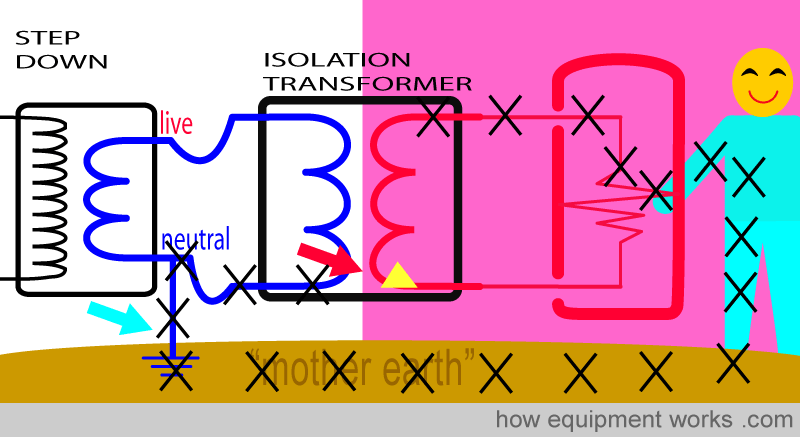
Now you may ask if the shock current (black Xs) can return to the source (yellow triangle) through the wire from neutral to mother earth (blue arrow) of the step-down transformer.
This does not happen because the isolation transformer prevents shock current from passing across from one side to the other (red arrow) to reach the source (yellow triangle). For this reason, our man remains shock-free!
As we have learnt before, transformers normally “transform” voltage to either lower or higher voltages.
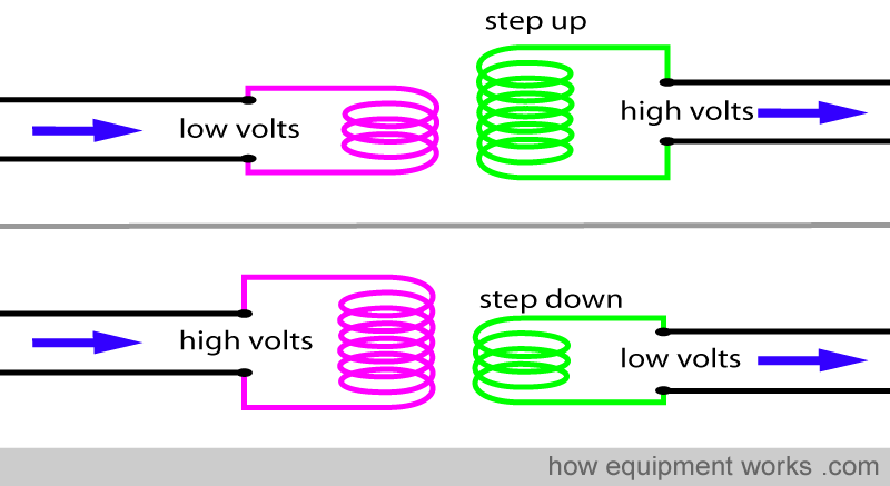
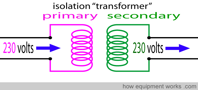
However, most isolation transformers are different. They neither raise nor lower the voltage. They have the same number of turns of wire on the primary and secondary sides and therefore do not change (i.e. do not transform) the voltage. Nevertheless, we still call them transformers, because they look so similar to other transformers that change voltage.
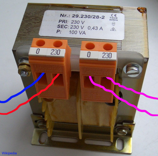
Below is a photograph of an isolation transformer. Note that the input voltage (230 volts) equals the output voltage (230 volts).
Micro shock
Some people get confused by macro shock and micro shock. Let me clarify things for you.
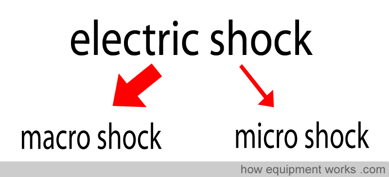
Electric shock can be subdivided into macro shock and micro shock.
The two main harmful effects of electric shock are burns and ventricular fibrillation. While both can be fatal, when we talk about macro shock versus micro shock, we generally are referring to the risk of ventricular fibrillation.
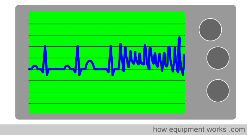
Ventricular fibrillation (VF) causing current can reach the heart in two ways. One route it can take is to go through the skin and tissues to reach the heart.
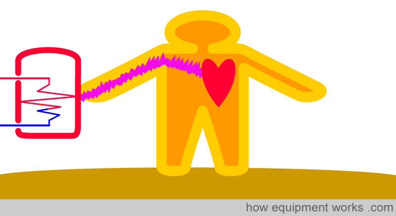
The other way is to give current straight to the heart without it having to go through the skin and tissues.

However, most normal human beings don’t carry their heart like a handbag where it could get a direct shock.

Instead, a shock may be given directly to the heart by something that conducts electricity very well, such as a pacemaker wire or a conducting fluid-filled tube such as a central venous pressure (CVP) catheter.
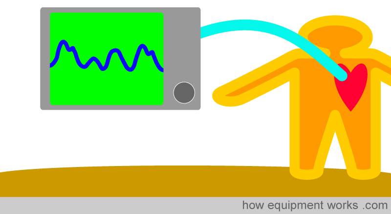
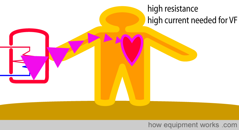
It is important to recognise that there is one big difference in the two routes described. The skin normally has a very high resistance to current flow. Therefore, for “enough “ current to reach the heart and cause ventricular fibrillation (VF), the current given to the skin has to be fairly large.
On the other hand, the shock current (pink arrows) that goes straight to the heart does not have to go through the high resistance of the skin. Instead, there is a low-resistance pathway straight to the heart. Because the resistance is low, only a small current is needed to cause VF.
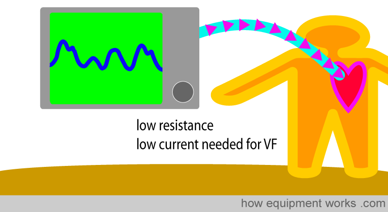
Macro shock is what most people refer to when they say “electric shock “. It is a shock that is large enough to go through the skin and tissues to reach the heart and cause VF. Of course, if applied directly to the heart, it will also cause VF.
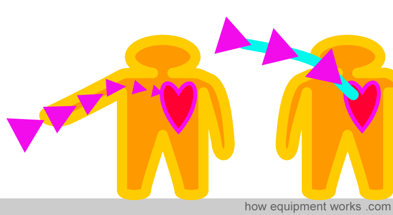
Microshock is different. Micro shock is NOT large enough to go through skin and tissue to reach the heart and cause VF. It however is large enough to cause VF if applied straight onto the heart. Micro shock involves very low currents such as 10 microamperes (i.e. 0.00001 amperes).
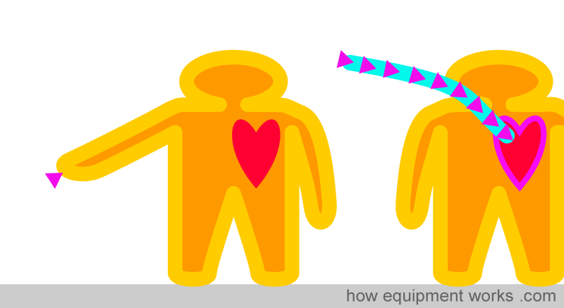
I hope this helps you to remember things:

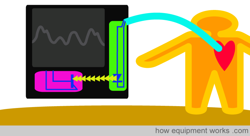
If equipment is expected to come into direct contact with the heart (e.g. external pacemakers, central venous pressure catheters) extreme precautions need to be taken to prevent microshock. These are highly technical design features that are beyond the scope of this website to discuss. For example, inside such equipment, circuits connected to the patient’s heart (green box) may use beams of light (yellow arrows) to communicate with other circuits that are not in direct connection with the heart (pink box). In that way, electrical shocks cannot pass from the red area to the green area. This type of arrangement protects the patient from even microshock currents.
Safety Classifications
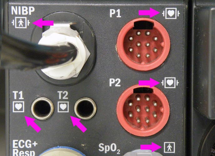
We have so far discussed a variety of safety protections. Safety protections can be classified in a variety of ways. You have already learnt some of these, but let me put common ones here in one place so that you will get a clearer picture. Please note that electrical safety is an area full of complex laws and regulations, so don’t use this stuff in the “real world”. You will often see symbols (see pink arrows) on medical equipment that may tell you what classification it belongs to.
There are two classifications that you might want to know about. One consists of three “classes” (green area below) and the other consists of three “types” (blue area).
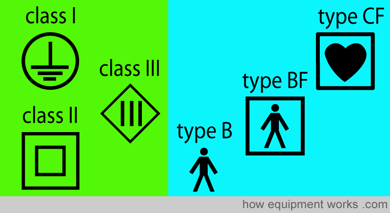
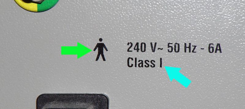
These classifications will be explained to you. Please keep in mind that these are two different classification systems. A piece of equipment can have a classification in both categories at the same time. For example, I took the picture below of an anaesthesia machine. Note that the markings on it tell us that it belongs to “Class I” (blue arrow) and also belongs to “Type B” (green arrow). Both the classification systems will be explained to you briefly.
Let us now briefly go through the classifications. First, we will talk about the “class system”.
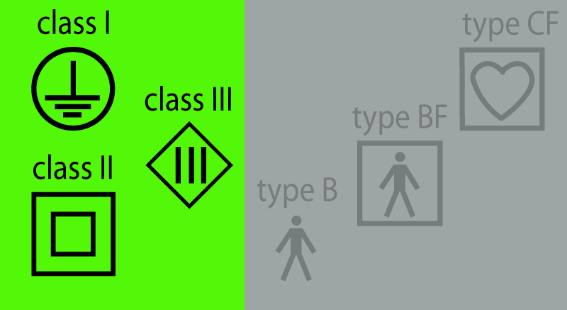
Class I: Equipment in this class makes use of the wire from the equipment case to Mother Earth to provide protection.
Class II equipment relies on at least two layers of insulation to provide protection.
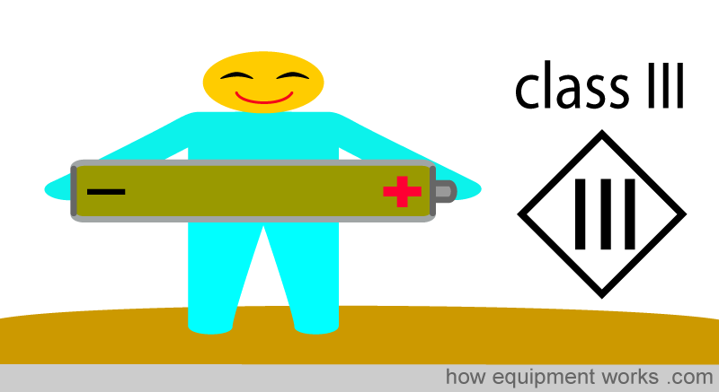
Class III equipment uses low voltages provided by batteries or special power supplies to be “safe”. Lower voltages are considered to be safer than high voltages.
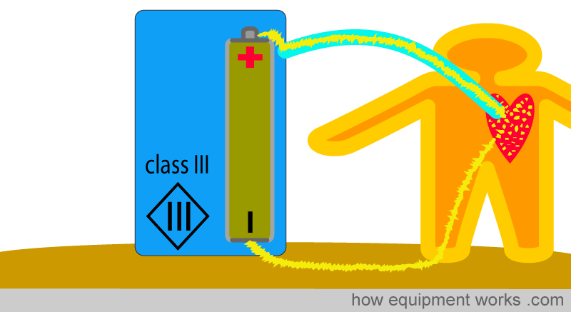
It is important to note that while class III equipment uses low voltages, that itself does NOT make them completely safe for medical use. For example, if a class III piece of equipment has a fault, its low voltages can easily cause microshock if applied directly to the heart.
Now let us discuss the other classification. Do remember that these two classifications are completely different to each other.

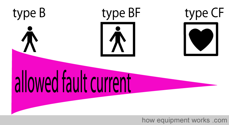
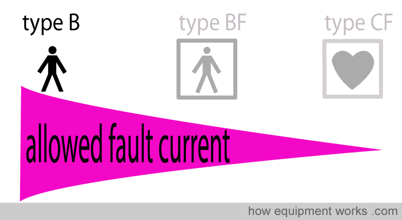
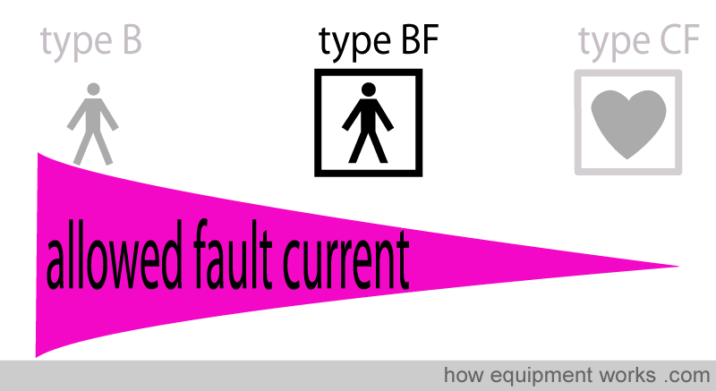
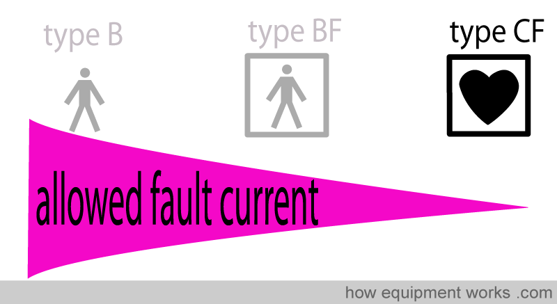
This classification describes how much shock current is allowed to come into contact with the patient or operator if a fault happens. Type B protection allows the most amount of shock current and type CF is the most strict, allowing very little shock current.
Type B (Body) protection:
This is the least stringent level of protection.
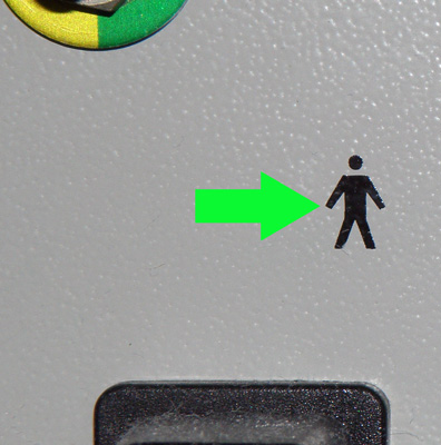
For example, the metal surface of the anaesthetic machine may have this level of protection. Below is a picture of an anaesthetic machine surface showing the symbol for type B protection.
Type BF (Body Floating) protection: This level of protection is more stringent than type B protection and is shown by the “man in the box” symbol below.
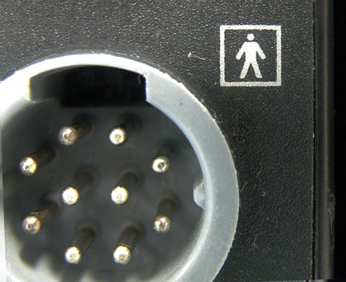
Below is a picture of a plug into which a pulse oximeter probe would normally be connected to. You can see from the symbol next to the plug that it has type BF ( Body Floating ) protection.
Type CF (Cardiac Floating) protection:
This is the most strict level of protection. Under fault conditions, it allows the least amount of shock current to enter the patient.
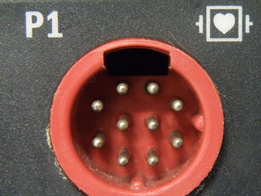
Below is a plug socket where one would plug in a central venous pressure (CVP) monitor. As you read before, a CVP catheter poses a threat of micro shock to the heart. Therefore, as you can see from the symbol (“heart in the box”), this plug has the highest level of protection, i.e.Type CF (Cardiac Floating) protection.
If you look at the symbol above, it has two “ears” on either side. I have shown them in red below.
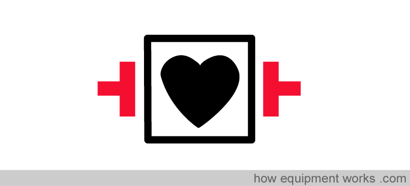
The “ears” on either side symbolise defibrillator pads. Defibrillation generates a very large current. The markings on the symbol indicate that the monitoring equipment can survive the shock of defibrillation.

Effects of electric shock
The effect of electric shock depends on the amount of current that flows through the victim. As the current increases, so does the degree of potential damage. Some of the effects are as follows.
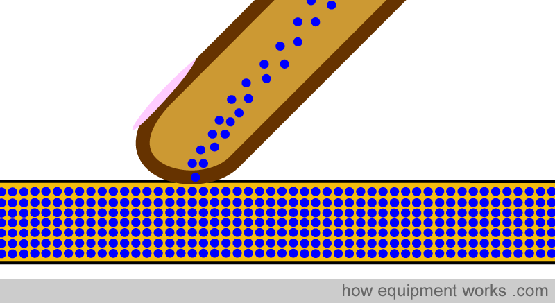
1. Tingling:
This is a “fuzzy “ feeling felt when in contact with an electric current. Even if you find it pleasant (hope you don’t), remove your body immediately, for the pleasantness may soon become unpleasantly fatal.
2. Pain :
This of course is a good thing because hopefully, you will move your body away from the source of the shock. In my case of electric shock described in the beginning, it was pain that made me move my arm away and save my life.

3. Muscle immobility :
If the electric current is strong enough to immobilise one’s muscles, it becomes difficult to move away from the source of the shock. This is very dangerous because the victim cannot protect him or herself. The level of current that immobilizes the muscles can be called the “cannot let go “ current.

4. Burns:
A high current flow can cause electrical burns. This can be worse than burns due to fire. In a fire burn, it is generally the areas directly exposed to the fire that burn.

With electrical burns, as the current travels inside the body, it burns tissues along the path. This can result in burns that may look minor from the outside while being deeply damaging inside.
5. Ventricular fibrillation:
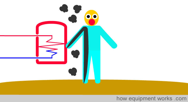
The heart itself uses electricity to communicate in an orderly manner. It is the organised passage of electrical signals that make the atria and ventricles contract effectively to provide a cardiac output. Electrical shock can disrupt this orderly passage of the heart’s own current. This may result in ventricular fibrillation, which if not treated, will be fatal.
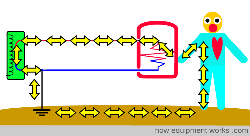
The likelihood of the electric shock to cause ventricular fibrillation depends on many factors. For example, the path that the current takes in the body influences the likelihood of fibrillation. In the example below, most of the current is not going through the heart, which is therefore less affected.
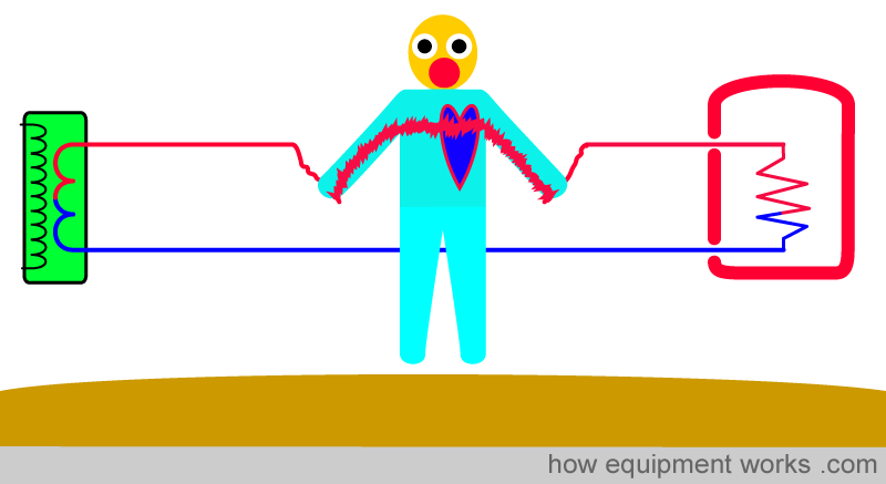
However, in the example below, the current is going right across the heart, increasing the risk of ventricular fibrillation.
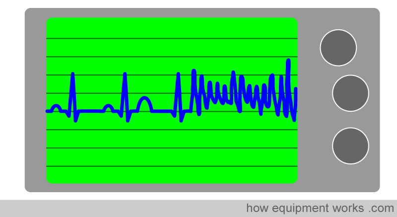
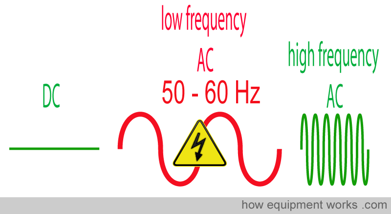
The risk of ventricular fibrillation also depends on the frequency of current. Low-frequency alternating current (AC), such as what typically comes out of a household or hospital power socket is the worst. Direct current (DC) (e.g. from batteries) and high-frequency AC (e.g. from electrosurgical / diathermy machines) is safer.
( If DC or AC doesn’t make sense, please read the “basic electrical concepts” part of this website).
What can you do for safety?
Some things you can do:
Visually inspect equipment for damage
Visually inspect wires for damage. Avoid subjecting them to physical stresses such as rolling equipment over them or pulling on them
Report any unusual sensations promptly.
Keep equipment dry unless they are specifically designed to be wet.
Wear appropriately insulated shoes.
Make sure your hospital engineering department does regular inspections.
Do not try to repair things yourself. A little knowledge can be a dangerous thing.
Make contingency plans for power failure.
Most importantly, if you suspect a fault, report it immediately to your engineering department. Never assume that “someone else” will do it.

How electricity saved me!
At the beginning, I mentioned how electricity nearly killed me. But electricity has also been kind to me as it once saved my life. It all happened during a very important anaesthesia oral examination. I was answering the questions well.

The exam was getting better and better……
And then disaster struck. I was asked a question that I just didn’t know the answer.

I was really stuck. It was something I just hadn’t read. And then, electricity helped me. There was a power failure ! Everything went dark.

Within a few minutes, the electricity supply came back. But by then, the examiner had forgotten the tough question. I passed the exam thanks to electricity helping me out!

Summary
Electricity can be dangerous, especially in the operating room, because there is so much electrical equipment around, anaesthetised patients cannot move away from danger, electric current is invisible, and there are fluids everywhere which can increase the risk of shock.
To get a shock, the person must be part of a circuit. The basic shock pathway helps us to understand this.
Insulation can prevent shock.
The earth wire (wire from equipment casing to Mother Earth) prevents shock by diverting current and also stopping the current flow by triggering devices that stop high current flow (e.g. fuses, circuit breakers)
Devices that shut off current by detecting differences in outgoing and returning current can protect even small current shocks. (e.g. residual current device, RCD)
Isolation transformers can protect a person by isolating one part of the circuit from another. The isolation transformer does not have a wire from neutral to Mother Earth and therefore does not provide a path for the shock current to return.
Electric shock can be classified as a macro-shock or micro-shock. If the patient is at risk of developing micro-shock (e.g. when using pacemaker wires or central venous monitoring), equipment designed to prevent micro-shock should be used.
Briefly discussed the physical effects of shock.
There are classifications that tell us about the nature of protection against electric shock a device has. Two such classifications, along with their symbols were discussed.
We have now reached the end of our discussion on electrical safety. I hope it has given you a good introduction to the subject and will help you when you read further on this topic. Hope to see you soon in another section. Bye for now.

Hello! My name is Pras and I am the author of this website that you are now reading. I have made this website completely free to access so that people from all over the world can benefit from it.
If you can afford it, I would be very grateful if you would consider making a single donation of one dollar (or the equivalent in your currency) to help cover the expenses needed to run this website (e.g. for special software and computers). For this website to survive, donations are desperately needed. Sadly, without donations, this website may have to be closed down.
Unfortunately, perhaps because many people think that someone else will donate, this website gets only very few donations. If you are able to, please consider making a single donation equivalent to one dollar. With support from people like you, I am sure that this educational website will continue to survive and grow.

