What is a vapour?
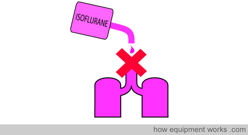
Inhalational anaesthetic agents need to be delivered to the lungs for them to work. Of course, one cannot simply pour them into the lungs!
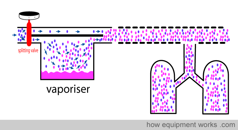
A much more acceptable way is to convert the liquid inhalational agent into a form that can be delivered by the inhalational route to the patient. The most convenient way is to deliver the “vapour “ form of the liquid inhalational agent. A device which converts liquid to vapour is called a vaporiser.
Before going on to discussing vaporisers, we need to first understand what a vapour is. And to understand what vapour is, we need to know about something called critical temperature.
If you take a gas and compress it really hard, the particles that compose it are brought ever so close to each other. As you keep compressing, the particles will at some point coalesce and convert the gas into liquid. However, if the gas is above a certain temperature, called a “critical temperature”, whatever amount of pressure you apply, that gas will not become a liquid. This temperature is called “critical temperature” and every gas has its particular critical temperature.
A gas that is currently below its critical temperature is called a “vapour “. If compressed with enough pressure, it will condense into a liquid.
A gas that is currently above its critical temperature remains a gas. However hard you compress it, it will not condense into a liquid.
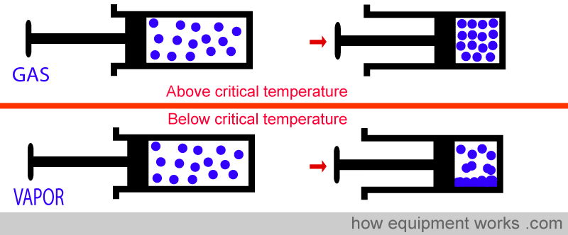
Let us take isoflurane as an example. The critical temperature of isoflurane is about 200 degrees centigrade. Therefore, at room temperature (e.g. 21 degrees centigrade), the gaseous phase of isoflurane would be called “isoflurane vapour “.
Now for a moment, let us imagine that you worked on the planet Venus. The surface temperature on Venus is about 500 degrees centigrade.

Now, because the “˜room temperature on Venus’ (500 C) is higher than the critical temperature of isoflurane (200 C), the gaseous phase of isoflurane would be called “isoflurane gas “.
Let us come back to Earth. If all this is confusing you, just remember, on Earth, at room temperature, all the gaseous forms of common anaesthetic agents exist as vapours.
Basic Vaporiser
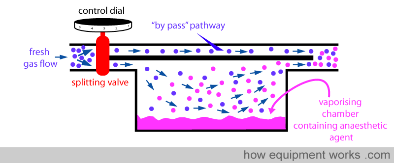
The purpose of a vaporiser is to add anaesthetic vapour into the fresh gas flow in a way that the output of the vaporiser delivers the set concentration of anaesthetic agent accurately.
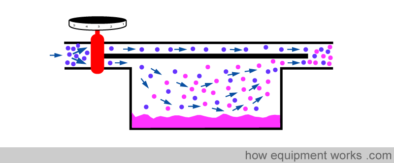
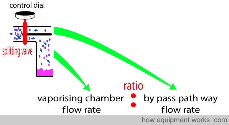
Fresh gas enters the inlet of the vaporiser and is divided into two flow pathways. The splitting valve, depending on the setting of the control dial, adjusts how much goes through each of the pathways. The fresh gas that is sent along the “bypass” pathway doesn’t come into contact with any vapour. On the other hand, the fresh gas that is sent to the vaporising chamber becomes fully saturated with vapour. At the exit end of the vaporiser, the bypass gas (vaporless) meets the chamber gas (fully saturated with vapour) and the two mix. The resultant output depends on how much fresh gas goes through each of the pathways.
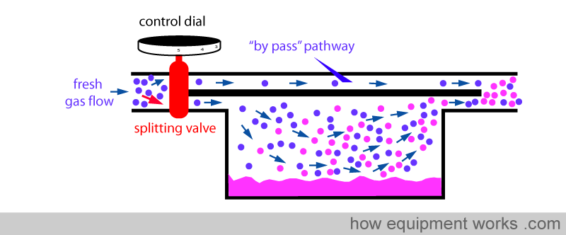
When you dial a high anaesthetic concentration requirement, the splitting valve sends more fresh gas via the vaporising chamber.
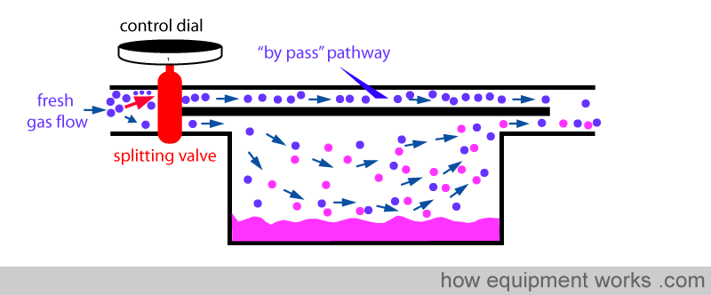
Similarly, when you dial a low anaesthetic concentration requirement, the splitting valve sends less fresh gas via the vaporising chamber.
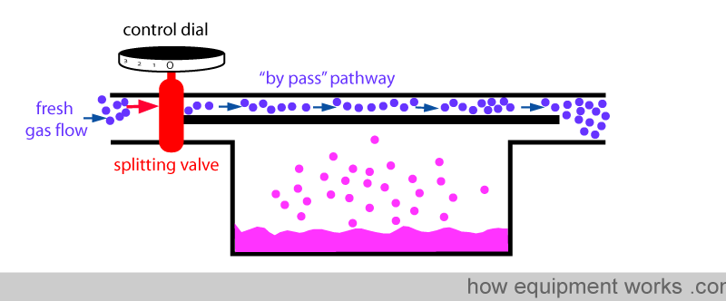
Finally, when you set the dial to zero to make the vaporiser deliver no anaesthetic vapour, the splitting valve sends all the fresh gas via the bypass pathway and nothing through the vaporising chamber.
You have seen that the anaesthetic concentration that is output by the vaporiser is determined by the ratio of the fresh gas flow that goes through the vaporising chamber and the fresh gas flow that goes through the bypass pathway. This ratio is called the ‘splitting ratio’.
Problems of the Basic Design
The basic vaporiser discussed above has a very simple design. Unfortunately, this simple design has the following problems:
- High flows of fresh gas going through the whole vaporiser can affect its output.
- The temperature of the vaporiser drops with use and this can affect its output.
- Some ventilators transmit a “positive pressure” back into the vaporiser which can affect its output.
The problem of high-flow
As discussed before, part of the fresh gas flow enters the vaporisation chamber and picks up vapour.
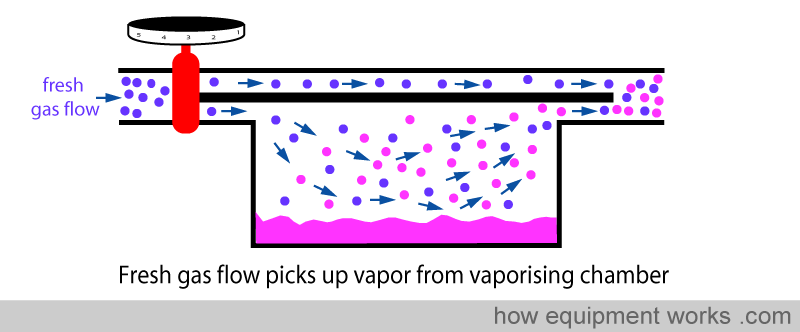
However, in the basic design, this vaporisation is not very efficient. If one uses a high fresh gas flow, the vaporisation process can’t keep up with so much gas arriving into the vaporisation chamber. The result is that, relative to the high flow of fresh gas flow, the amount of anaesthetic vaporised is inadequate. So this means that at high flows, the basic vaporiser delivers less anaesthetic concentration than is set on the dial.
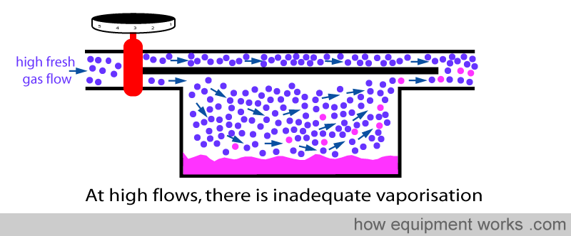
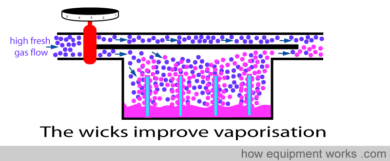
The solution employed by modern vaporisers to solve this problem is to make the vaporisation much more efficient by increasing the surface area of contact between the fresh gas and the anaesthetic agent. So even when there are high flows, efficient vaporisation means that all gas going through the vaporisation chamber is fully saturated. Because of this ability to saturate fresh gas at all flow rates, the output concentration remains accurate to the setting on the dial over a wide range of flows. I.e. The output concentration is independent of flow.
One method that vaporisers use to increase the efficiency of vaporisation is to dip wicks into the anaesthetic agent. Due to capillary action, the anaesthetic agent rises into the wicks. This dramatically increases the surface area of the anaesthetic agent exposed to the fresh gas entering the vaporisation chamber and thereby improves the efficiency of vaporisation.
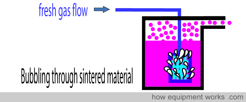
Certain vaporisers (e.g. “Copper Kettle”) use bubbles to increase the surface area for vaporisation. In these, some of the fresh gas flow is bubbled through a disk made out of a special material (sintered disk) that is very porous. The disk is submerged into the anaesthetic agent and when fresh gas is sent through it, a large number of tiny bubbles form. The tiny bubbles of fresh gas have a very large total surface and thus become fully saturated with vapour efficiently.
The problem of temperature
For vaporisation to occur, the anaesthetic molecules have to “escape” from the liquid state and become vapour. This process reduces the ‘energy’ left in the remaining liquid.
As more and more molecules escape, more and more energy is lost from the liquid. The temperature of a liquid is a measurement of how much ‘heat energy’ the liquid has. Therefore, as the escaping molecules reduce the energy left in the liquid, the temperature of the liquid falls.
The falling temperature (lowering energy) of the liquid means that fewer molecules are able to escape. i.e. as vaporisation happens, the temperature of the liquid falls causing less vaporisation.
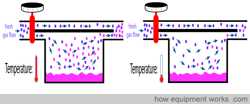
The less vaporisation then will decrease the concentration of anaesthetic delivered by the vaporiser. I.e. It will deliver an anaesthetic concentration below the setting you dialled.
There are two common solutions to this problem.
One is that we can give heat to the liquid to minimise the temperature drop.
The other is to increase the flow of fresh gas into the vaporising chamber to compensate for the reduced vaporisation efficiency of the cold fluid.
‘GIVING HEAT’
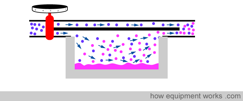
In most vaporisers, we don’t actually give heat “actively”. That is, we don’t electrically heat it (complicated and needs a power supply) and nor do we light a fire under it (absolutely dangerous). Instead, we make it easy for the vaporiser to use heat from the surrounding air.
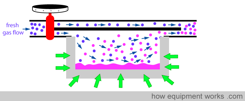
The vaporising chamber is generally surrounded by a lot of metal.
The metal helps to minimise the temperature drop in two ways. Firstly metal is a very good conductor of heat and therefore is able to efficiently transfer heat from the surrounding air into the anesthetic agent.
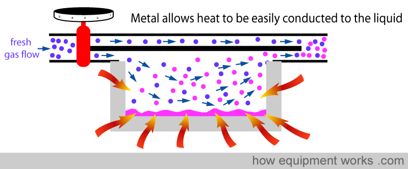
Secondly, metal acts like a ‘heat store’. It ‘absorbs’ heat (green arrows) till its temperature equals the temperature of the surrounding air.
When the anaesthetic agent starts to cool, the metal now ‘donates’ heat ( yellow arrows ), helping to minimise the temperature drop.
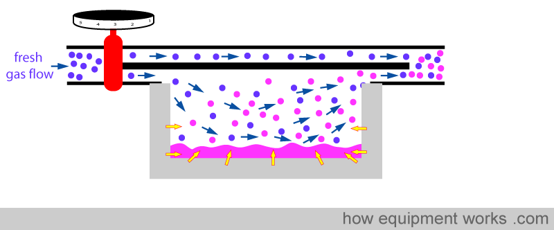
However, the metal casing cannot give up heat indefinitely and after some time, its temperature also drops.
In between your anaesthetic, when you turn the vaporiser off and have coffee before your next case, the metal will continue to “absorb” heat from the surroundings and its temperature will rise, ready to donate heat when you turn the vaporiser on again.
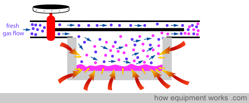
So in summary, the metal provides heat to minimise the temperature drop in two ways. One way is by ‘donating’ heat to the fluid (yellow arrows) and the other way is by conducting heat (red arrows) from the surrounding air.
GIVING MORE FLOW
When the temperature of the liquid agent drops, we have seen that the output concentration of the vaporiser drops. A way of compensating for that problem is to increase the flow of gas via the vaporising chamber (altering the splitting ratio). One could manually do this by measuring the temperature of the liquid with a thermometer and increasing the dial setting according to some kind of reference chart. This would be quite tedious as you would have to do it all the time. Modern vaporisers have removed the hard work. When the liquid drops its temperature, the flow of gas through the vaporising chamber is automatically increased without you having to turn the dial.
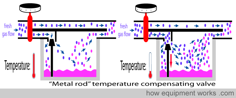
This is accomplished by an automatic temperature-compensating valve that influences how much flow goes via the vaporising chamber.
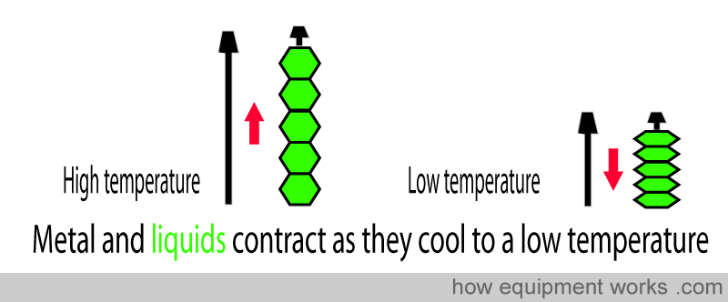
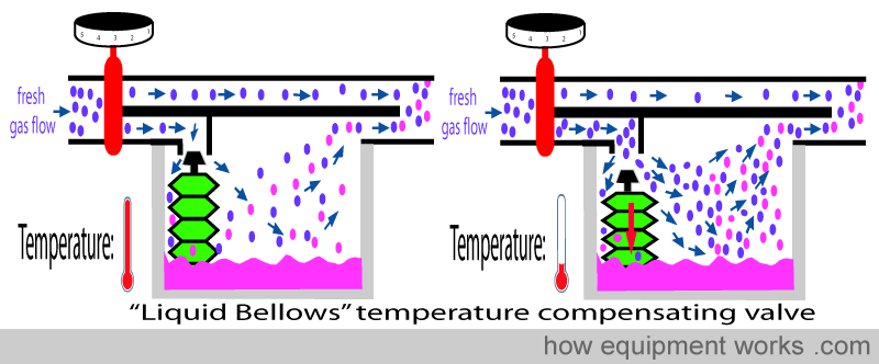
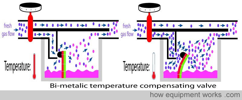
The automatic temperature compensating valve uses the physical property that substances (e.g. metals and liquids ) become smaller when the temperature lowers. A metal rod (shown in black below) shortens as the temperature drops. Similarly, a liquid filled in collapsing bellows (shown in green below) becomes smaller in volume when cooled to a lower temperature.
This property is used in the design of automatic temperature-compensating valves in vaporisers. In the design that uses a metal rod, the rod offers some resistance to flow into the vaporising chamber. As the vaporiser cools, the rod becomes shorter, making the valve move away from the opening. This reduces the resistance to flow and thus more flow occurs into the vaporising chamber.
Some vaporisers use the expansion or contraction property of a special liquid inside bellows (shown in green) to control the valve. As the temperature falls, the liquid in the bellows contracts into a smaller volume. This makes the bellows shrink, pulling the valve away and thereby increasing flow.
Another method uses a “bi-metallic” strip. Different metals expand and contract to differing extents when exposed to temperature changes. In the example below, the “green” metal expands and contracts more than the “red” metal.
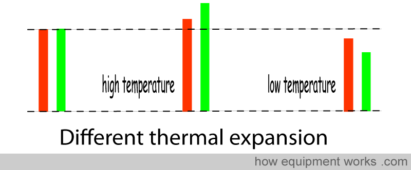
In a bimetallic strip, two metals with very different degrees of thermal expansion ( “different coefficients of thermal expansion” ) are fixed together. In the example below, when the temperature drops, the “green” metal contracts much more than the “red” metal. Because they are fixed together, they cannot contract independently, like in the diagram above. Instead, the “green” metal “tries” to drag the “red” metal and causes the bimetallic strip to bend.

In the vaporiser, the bimetallic strip is fixed in such a way that it offers a resistance to flow entering the vaporising chamber. When the temperature of the vaporising chamber drops, the bimetallic bends and moves away. This reduces the resistance to flow and thus more flow occurs into the vaporising chamber.

Do you work in the anaesthetic team? If you do, please visit the free website below, which has anaesthesia-related fun and safety material. Click the button below to visit.

The “pumping effect”
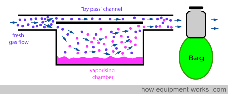
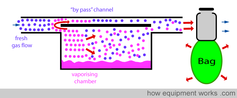
Positive pressure ventilation results in intermittent pressure changes. During the positive pressure, there is a pressure rise and during expiration, there is a sharp drop in pressure. These pressure changes can be transmitted back into the vaporiser and can affect the concentration of the anaesthetic agent delivered. The effect of changing pressure affecting the output of the vaporiser is called the “pumping effect”. In this section, this effect and the methods used by vaporiser designers to prevent it from happening are explained. Below is shown a basic vaporiser and a bag beyond to represent positive pressure ventilation.
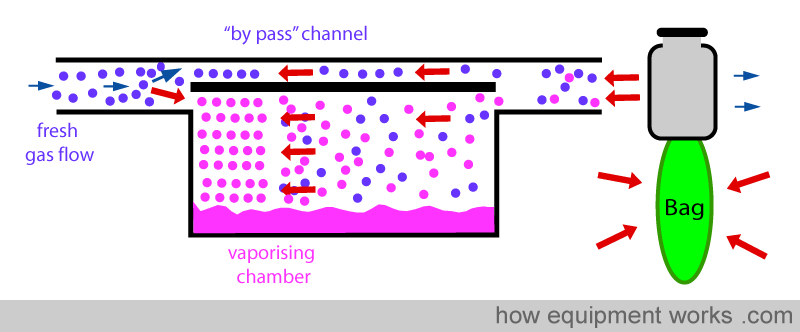
When the bag is squeezed (positive pressure ventilation), pressure is transmitted back into the vaporiser as shown below. This “back pressure” is transmitted to both, the “bypass” channel and also to the vaporising chamber. This “back pressure” opposes the flow of the fresh gas in both the “bypass” channel and the vaporising chamber. The fresh gas entering the vaporiser tries to move forward and gets compressed both in the ‘bypass’ channel and the vaporising chamber. However, the vaporising chamber volume is much larger than the ‘bypass’ channel volume, and thus, more fresh gas gets compressed into it than into the ‘bypass’ channel.

This extra fresh gas that enters the vaporising chamber collects anaesthetic vapour.
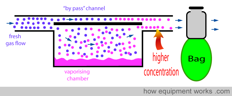
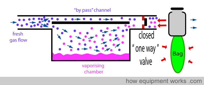
Now see what happens when the positive pressure is suddenly released (expiration). The previously compressed gases now suddenly expand in all directions.
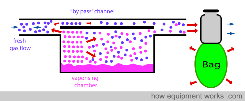
Some of the rapidly expanding gas (containing vapour) enters the inlet of the vaporiser and crosses over into the ‘bypass’ channel as shown below.
Normally, a vaporiser’s ‘bypass’ channel does not have vapour. So this vapour due to the ‘pumping effect’ is additional. When this ‘bypass’ vapour flows across to the exit of the vaporiser, it meets the vapour from the vaporising chamber. The addition of the ‘bypass’ vapour to the vapour from the vaporising chamber raises the final concentration of the anaesthetic delivered. i.e. The ‘pumping effect’ increases the delivered concentration of the anaesthetic agent.
Vaporiser designers have various tricks to reduce the ‘pumping effect’ and some of these are discussed below:
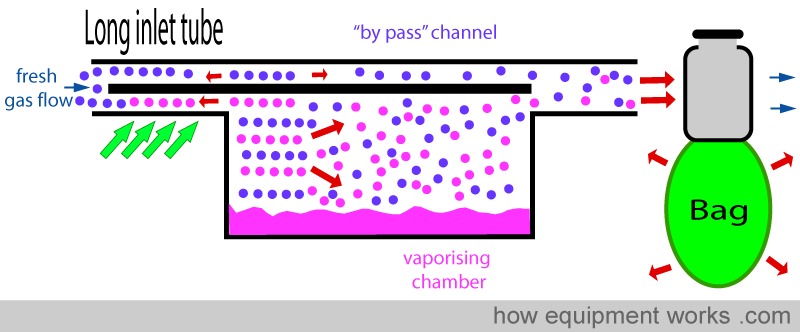
LONG INLET TUBE
The vaporiser inlet tube can be made longer. When the ‘back pressure’ is suddenly released during expiration, as discussed before, the extra gas in the vaporising chamber will suddenly expand. However, thanks to the long inlet tubing, the extra gas containing vapour expands into the long inlet tube and doesn’t reach the ‘bypass’ channel.
INCREASED RESISTANCE
The vaporiser can be designed to have a high internal resistance to flow. This high resistance “resists” changes to flow caused by the intermittent ‘back pressure’ of positive pressure ventilation.
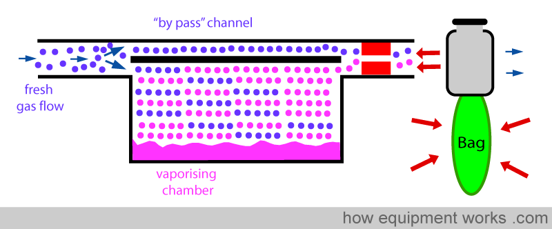
ONE-WAY VALVE
A ‘one-way’ valve (also called a unidirectional valve) can be put between the vaporiser outlet and the ventilator/breathing system. On-way valves allow flow in one direction, but not in the other. In the diagram below, the one-way valve allows gases to flow forward.
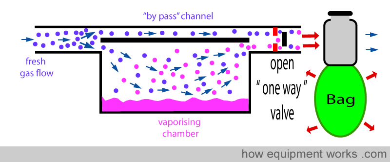
However, this valve prevents flow from occurring in the reverse direction. This reduces the transmission of ‘back pressure’ to the vaporiser.
Please click the “Next” button below to read part 2 about how anaesthesia vaporisers work. Thank you.