We will discuss the following aspects. Please scroll down and start reading (and enjoy !):
- What are capacitors and why we use them in defibrillators.
- How capacitors are charged and discharged.
- How the defibrillator creates the “biphasic truncated exponential waveform”.
- A brief introduction to “automated external defibrillator” (AED).
- A brief introduction to “implantable cardioverter defibrillator” (ICD).

Have you noticed cats often do mysterious things, like throwing things off shelves, staring at things endlessly, and mysteriously appearing at various places? The amusing website at the link below explains how cats are more than cute little things; instead, they control the universe using their superpowers. Visit the free website below to discover the secret world of cats.

Introduction
We all know that electrical currents can kill a person. However, electrical current given using defibrillators can save lives. The human heart can develop an extremely serious condition called “ventricular fibrillation”, which if not treated, leads to death in minutes. A defibrillator is a device which, as its name suggests, can stop ventricular fibrillation. If you are not a medical person and want to know simply, what ventricular fibrillation is and how defibrillation stops it, please click here.
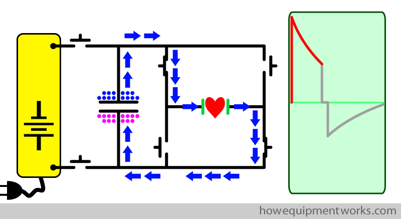
On this page of the website, you will learn the basic physics of how a defibrillator works. In the end, you will be able to understand and draw the basic circuit of a defibrillator as shown below. Please do not get a heart attack seeing this diagram! I will explain it step by step and you will understand it all.

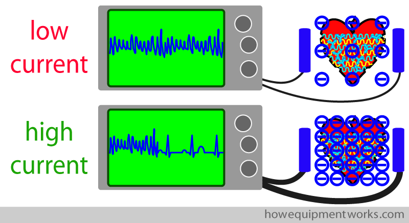
To defibrillate a heart, one needs to pass a very large current through the heart to silence the heart muscle cells. A low current would not work.
The need for a “capacitor”
A major design requirement of defibrillators therefore is to have the ability to provide the large current needed to defibrillate a heart. A crucial electrical component in defibrillators that makes it possible to deliver huge currents is a device called a “capacitor”.
To explain what a capacitor is, I would like you to imagine that you are a fireman (or firewoman!). Shown below is you, proudly wearing your red fireman’s uniform. Next to you is a water pipe, which of course will be your main weapon to combat any fires you will face. Like all visitors to this website, you are a dedicated worker and are happily waiting for your first fire.

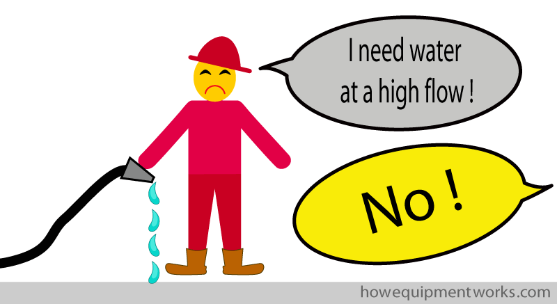
While waiting for the first fire to happen, you decide to test your equipment. You turn on the water supply and to your surprise, the water flow is very low. Thinking that there must be some fault, you immediately tell your boss about it. She tells you that, to save money, she will only provide a low flow of water. You plead with her for a higher water flow, and all she says in response is; “No !”
While you were arguing with your boss, a real fire needs your urgent attention. You run with the water pipe and let the water flow into the fire.
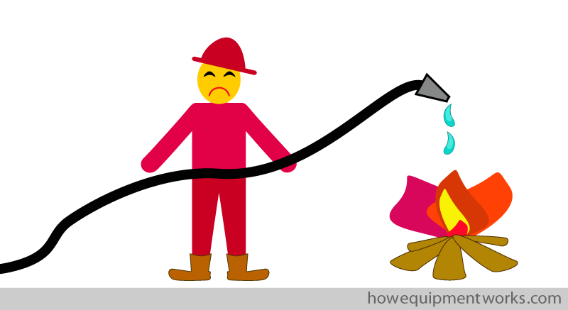
Well, you are not surprised that the low water flow is not putting the fire out. Just as you told your boss, the water flow is simply not enough to put the fire out. In fact it appears that the fire is laughing at you!
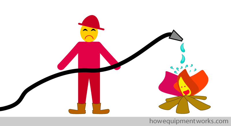
You are not the type who gives up and you start to think about a solution. The water that is being supplied to you is coming at a continuous low flow. However, what you need is a brief high flow of water that will once and for all put the fire out.

You suddenly think of a great solution. With your own money (you know your boss won’t give you any) you buy a bucket! You then do the following things. I will show the things you do in some detail as it will be relevant when we discuss the role of the capacitor in defibrillators. First, using the “continuous low flow” supply of water, you start filling the bucket.

After a little while, you have a bucket that has been filled with enough water to put the fire out.

Now you tip the bucket over the fire. A brief but high flow of water falls onto the fire, putting it out. You have won the battle! Your boss is happy and “promises” to pay for the bucket someday.

Now that you have put the fire out, let us return to defibrillators. As you may have guessed, there are some “similarities” between putting the fire out and defibrillation. As a fireman, to successfully put the fire out, you needed a brief large flow of water. In a similar way, as you learnt earlier in our discussion, you need a brief large current to defibrillate a heart.
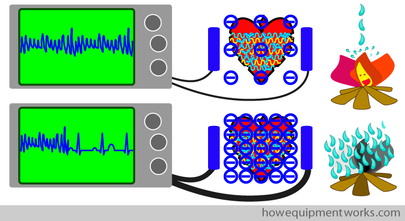
You will recall that when you were a fireman, the big problem you had was that the water supply provided to you had a very low flow. Without the bucket, this low water flow was simply not enough to put the fire out. The bucket was your saviour!
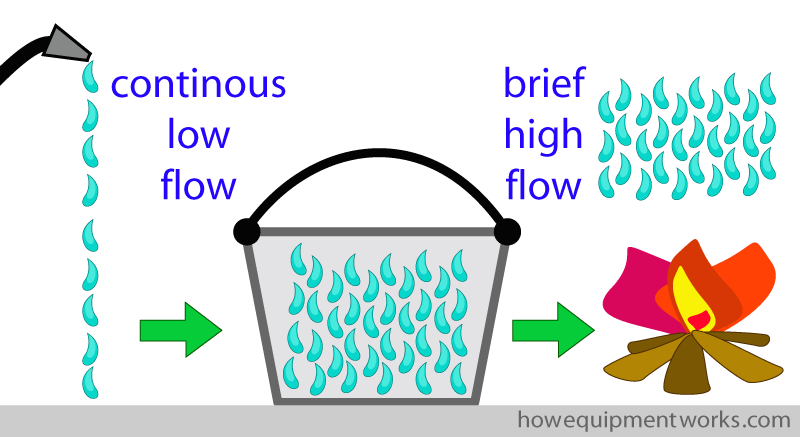
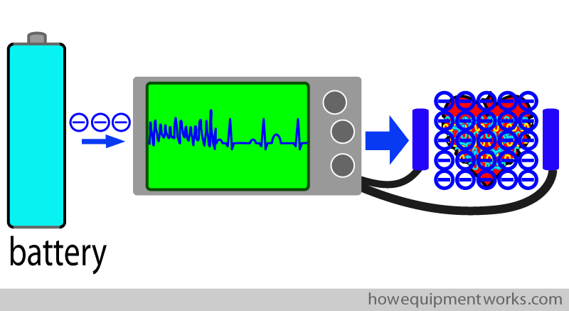
The designers of defibrillators face a similar problem to the low-flow water supply you faced as a fireman. All electronic devices, including defibrillators, need a source of power (current) to work. For example, because defibrillators have to be easy to transport, they often get their power from batteries. Unfortunately, batteries can only produce a continuous low flow of current. The defibrillator has to “somehow” use the continuous low-flow current from the batteries to provide the brief high-flow current needed for defibrillation.
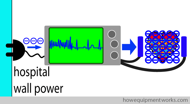
Defibrillators can also get power from the wall sockets in your hospital. However, even the maximum current available from such wall plugs is not enough to directly produce the high current flow required for defibrillation. I will further explain this.
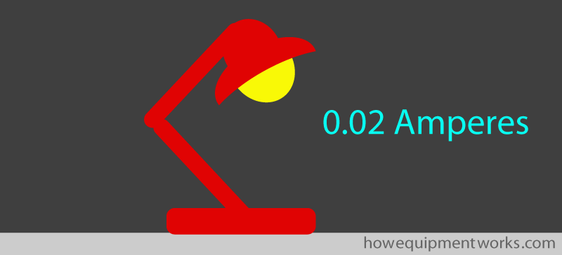
As a very approximate example, the current needed for defibrillation can be in the region of 20 A (Amperes). So how big is a current of 20 A? Shown below is a diagram of a table lamp. A modern lamp such as this consumes about 0.02 Amperes.
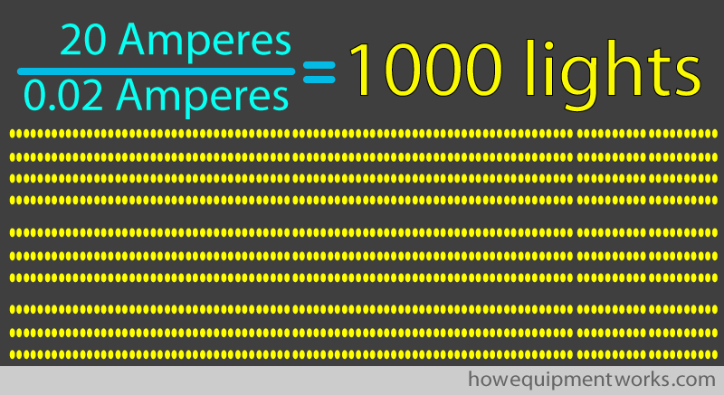
As shown below, when you do the calculations, you will see that the 20 A defibrillation current equals the current consumed by approximately 1000 table lamps! So even when the defibrillator is plugged into a wall power socket, the current from the socket cannot be used directly to provide the huge current needed for defibrillation. How the defibrillator is able to produce the large currents needed for defibrillation from batteries or wall power sockets involves some magic which I will reveal to you soon! By the way, please do not learn the numbers shown below as they are very approximate.
At this point, I would like to “warn” you that the discussion ahead will involve us dealing with some basic electrical concepts. Hopefully, this is not too surprising to you as defibrillation is all about electricity! However, do not worry too much if electricity frightens you as I will try and keep things as simple as possible. Also, this website has a separate section explaining the “basics of electricity”. If words like current, potential difference, alternating current and direct current make little sense to you, it might be a good idea to first visit the “basics of electricity” section of this website by clicking HERE (please remember to come back!).
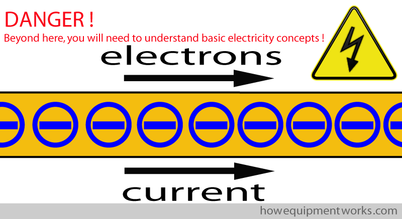
When you were a fireman, the bucket was the saviour. The defibrillator needs the electrical equivalent of the bucket. It needs something that can collect the continuous low flow of current from batteries or wall power and then release it as a brief large flow of current.
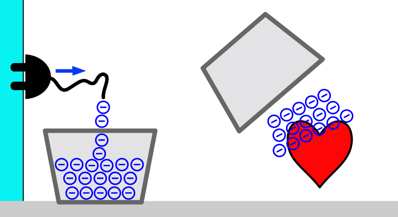
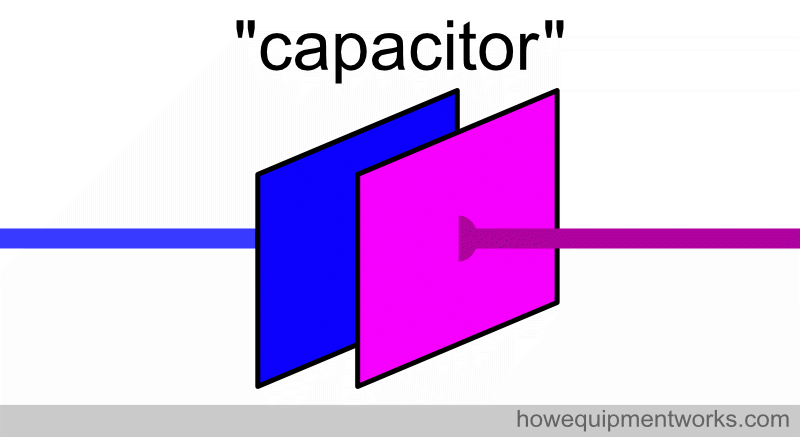
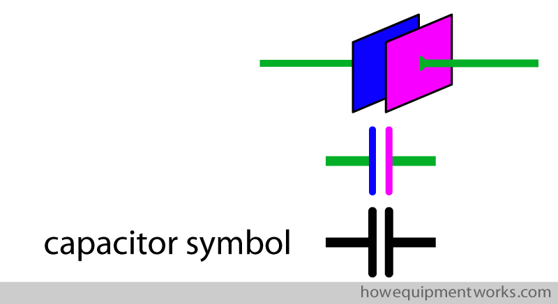
Fortunately, there is such a device and it is called a “capacitor”. Capacitors play an extremely important role in defibrillators and I will of course explain to you how they work. The capacitor in a defibrillator is able to collect the continuous low flow of current, store what it has collected, and then release it as the brief large flow of current needed for defibrillation. The basic design of a capacitor is extremely simple. It consists of two parallel flat metal plates, shown below as blue and pink squares. Wires (shown in green) are connected to each of the plates.
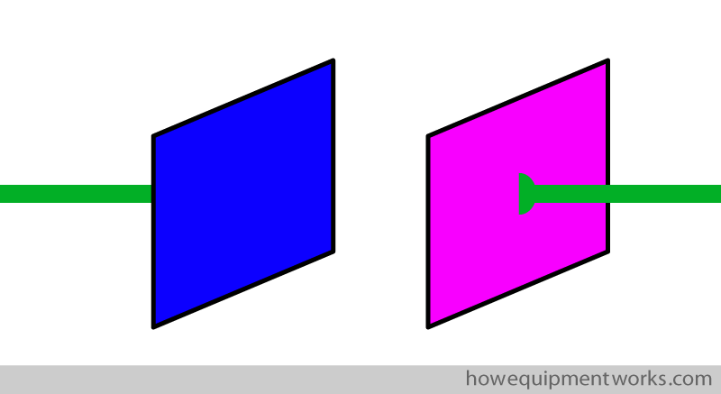
The metal plates lie very closely next to each other. In real life, the plates are so close to each other that you would need a magnifying glass or microscope to see the separation. I, however, cannot draw them so close, so do remember to use your imagination when you see my diagrams.
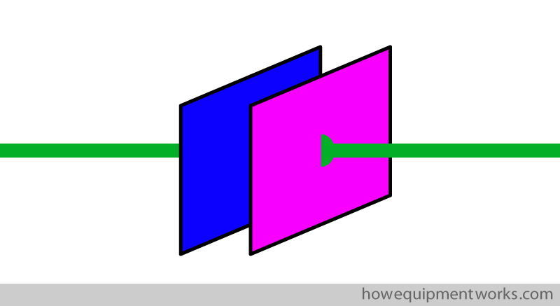
In the world of electronics, when a circuit is drawn, symbols are often used to represent various devices. Fortunately for us, the symbol representing a “capacitor” is very easy to remember as it looks so much like the object it represents.
How capacitors work
As explained before, a capacitor consists of two metal plates lying next to each other. To know how capacitors work, we need to first understand how a metal can become “electrically charged”. The actual physics of how this happens is somewhat complex and it is not necessary for our purposes to understand it in great detail. If you struggle to understand what I explain in this section, please just skip it and move on to the next section. Let us start! Metals have “positive charges” and “negative charges” inside them.
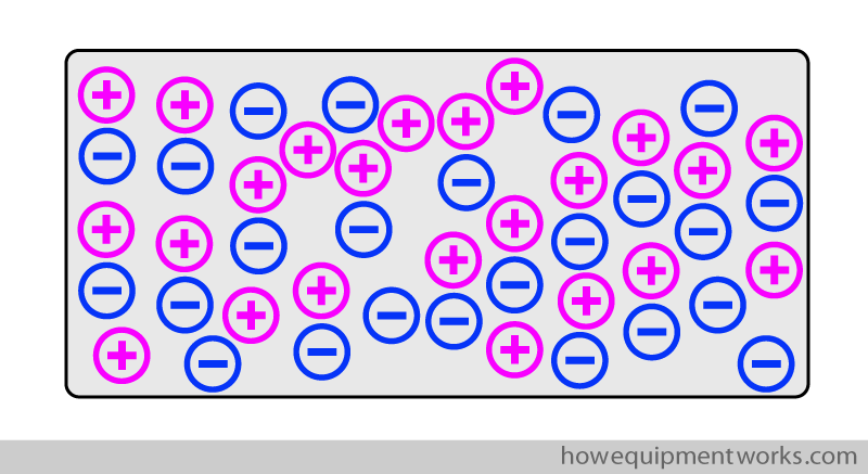
I would like you to, only for this discussion, think of the charges inside the metal as being very romantic boys and girls! The negative charges and positive charges are strongly attracted to each other. Given any opportunity, the opposite charges would love to form a relationship and be together as a happy couple!
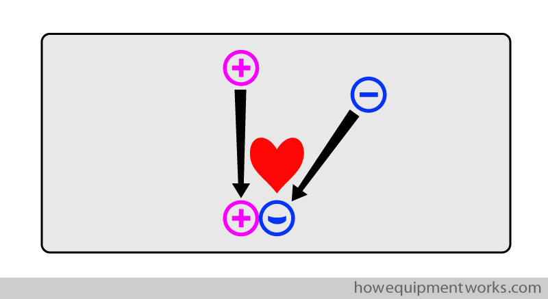
However, the positive charges are very “lazy”. Let me explain! Say that in the metal, there are positive charges at one end and there are negative charges at the other end. As explained before, the positive charges and negative charges are attracted to each other and they would like to be together to form a happy couple. In this situation, you would expect both charges to move towards each other.
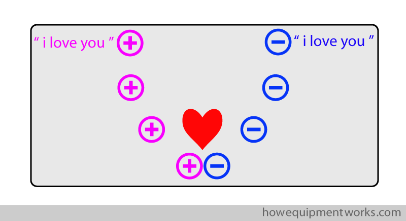
However, what happens is that only the negative charges move to be with the positive charges. The positive charges stay fixed in one place, which is why I call them “lazy”.
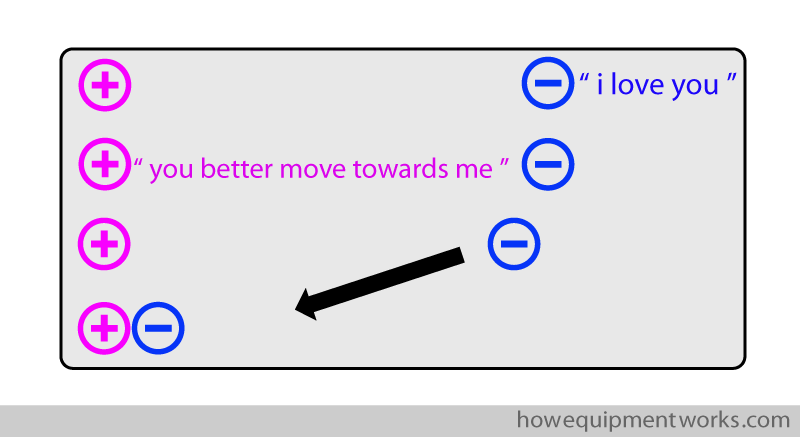
The same situation exists when a positive and negative charge couple split up. Say a negative charge is interested in another positive charge (negative charges are not very faithful !). When the negative charge leaves the positive charge to be with its new lover, the positive charge it was with will not “follow” it. It just lazily remains fixed in one place.
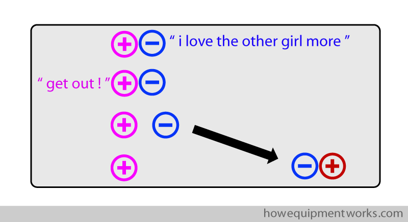
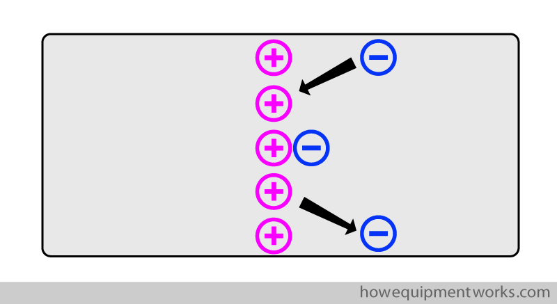
So basically, when attracted to each other or when leaving each other, it is only the negative charges that move.
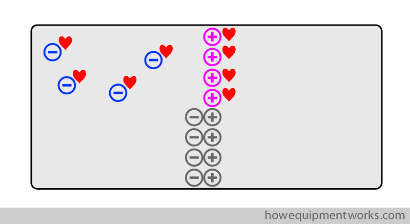
From a physics point of view, we are not interested in the happy couples (i.e. where a negative charge is together with a positive charge). These “happy couples” (shown in grey below) are for the moment stable. What interests us are only the charges that do not have a partner (i.e. the ones who are lonely and are desperate for a partner, shown below with hearts). It is these single “available” charges that are active in electrical circuits.
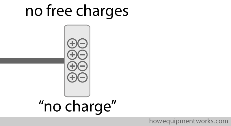
Now let us understand what we mean when we refer to the “charge” of a metal plate of a capacitor. Shown below is one metal plate of a capacitor. I have drawn this plate as a very thick one as this will help me to explain things better. A metal plate of a capacitor can have no charge, be positively charged, or be negatively charged. Let us first start by seeing a metal plate with “no charge”. Such a plate has an equal number of positive and negative charges inside it. Being “romantic”, these charges form “couples” and therefore there are no extra positive or negative charges left. As mentioned before, in physics, we are only interested in extra positive or negative charges. When we refer to the “charge ” of a metal plate, we are actually referring to how many extra “free” positive or negative charges are there. Since the metal capacitor plate in the example below has no extra charges, we can say that this plate has “no charge”.
Let us now make a capacitor by putting another metal plate next to the plate we saw before. Since this new metal plate also has no extra charges, we can also say that it has “no charge”.
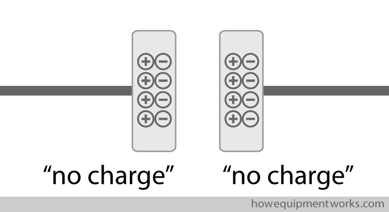
A capacitor with “no charge” in it has no energy for defibrillation. It is like an empty water bucket that needs to be filled before it can be used to put a fire out.
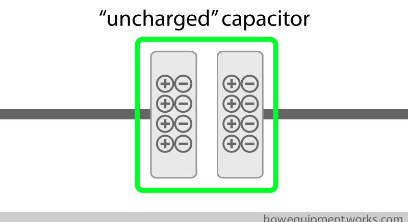
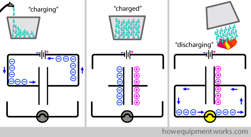
A capacitor needs to be “charged” before it can be used to provide current for defibrillation. Charging a capacitor is the equivalent of filling the bucket with water. During charging, electrons (i.e. current) goes into the capacitor and collect there (i.e. get stored).
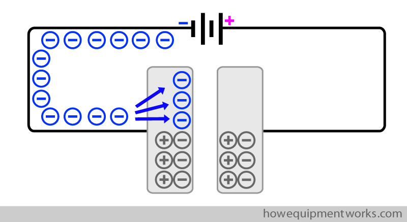
Shown below is a capacitor that has been “charged”. In this “charged” capacitor, plate A is “negatively charged” (because it has excess free negative charges) and plate B is “positively charged” (because it has excess free positive charges). In this charged state, the capacitor is capable of giving the necessary current required for defibrillation. In the sections that follow, I will explain to you how a capacitor is charged, and then, how it can release that charge (discharge).
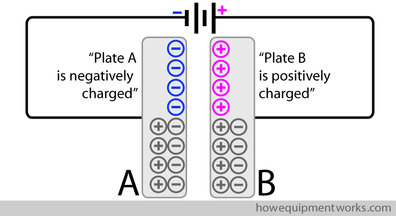
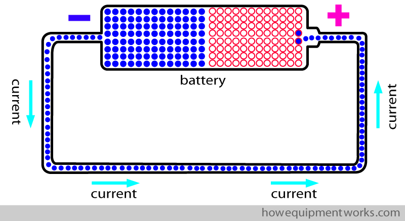
To understand how a capacitor is charged, let us first recall some basics about electricity. You will remember that electrons flow only when there is a potential difference across the wire that carries them. Shown below is a battery, which as you know, is something that provides a potential difference. Here the potential difference provided by the battery is making the electrons (current) flow in the wire.
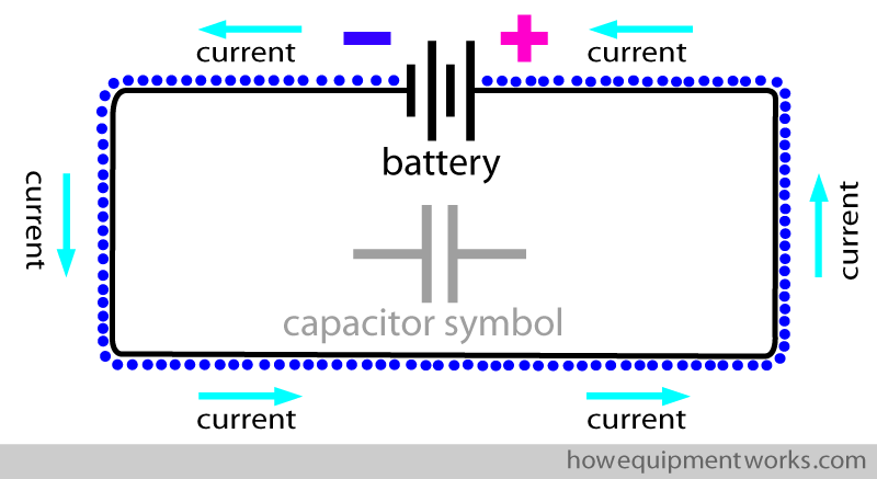
It is quite messy to draw a battery looking like the one above. So instead, I will use the international symbol that represents a battery. Please note that the battery symbol looks somewhat similar to the capacitor symbol, which I have shown in grey for you to compare.
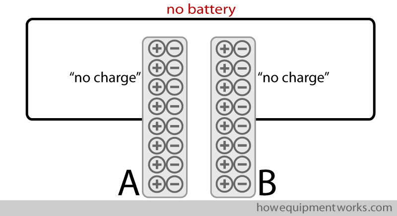
We will soon connect our capacitor to a battery to see what happens. However, before that, let us see what happens when we connect the capacitor to a wire that has no potential difference (i.e. there is no battery). As shown below, both plates of the capacitor have no extra charges. In other words, both plates have “no charge”.
Now let us connect the capacitor to a battery. The battery creates a potential difference across the capacitor. As I will explain to you soon, interesting things will happen on both plates of the capacitor.
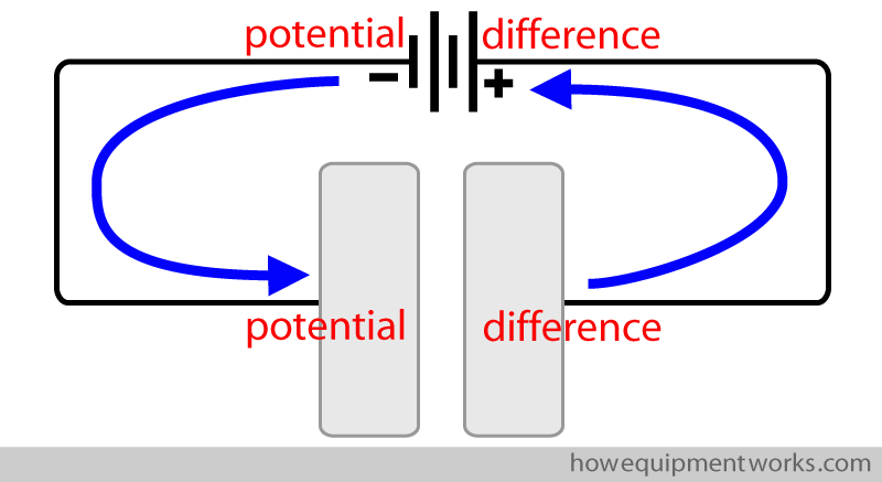
To make things easy to explain, I have labelled the plates of the capacitor as “A” and “B”. Let us first see what happens at plate B. Because of the potential difference, the negative charges (electrons) in plate B are attracted to the battery. These electrons (which are not very loyal to their partners !) leave their positive charges and go to the battery. You will recall that the positive charges, being lazy, don’t run after electrons that leave them.
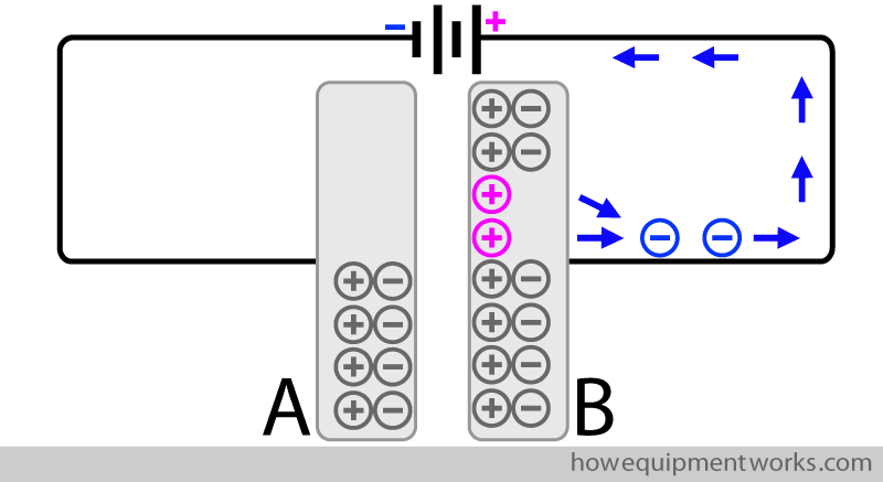
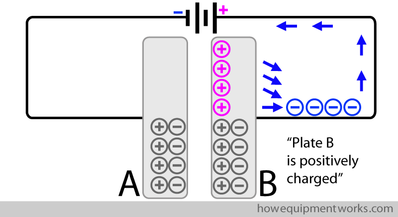
As you can see below, because electrons have left plate B, there are now free positive charges in this plate. Therefore we can say that plate B is “positively charged”.
Now let us see what happens in the other plate (i.e. plate A). The electrons in the battery are “attracted” to the positive charges on plate B. These electrons therefore go from the battery towards plate A, “hoping” to meet the free positive charges on plate B.
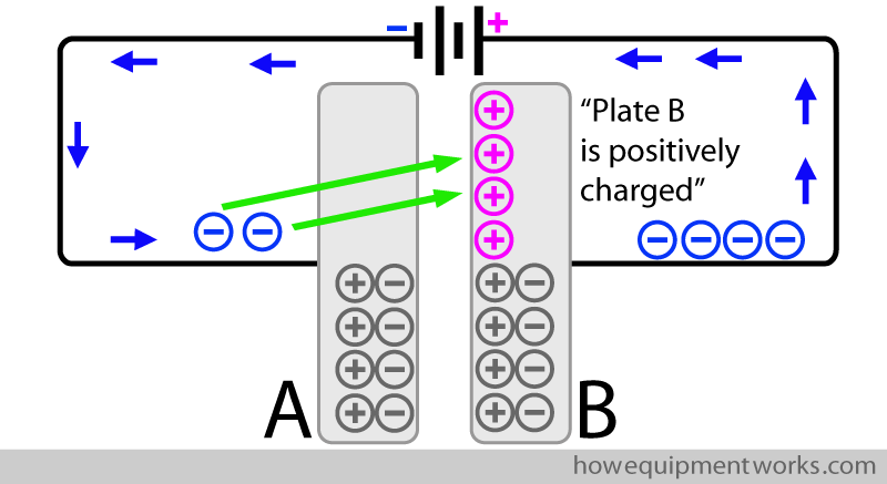
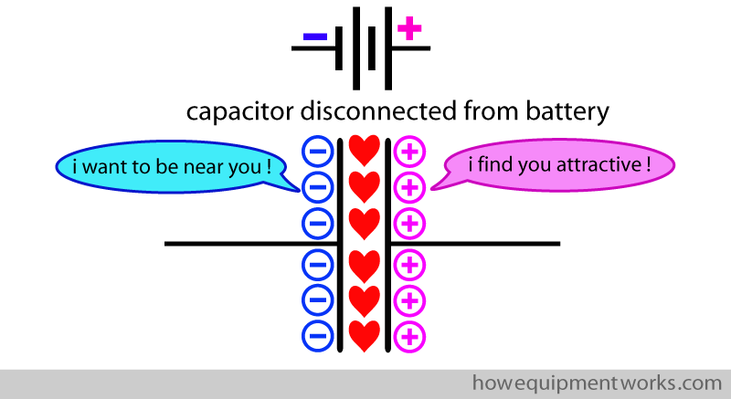
However, the electrons from the battery cannot cross from plate A to plate B as there is a gap between the two plates. So while the electrons in plate A are attracted by the positive charges in plate B (attraction shown as hearts in the diagram below), they can only “admire” them from across the gap. This attraction between the charges is only possible because the plates in real life, unlike what is shown in my drawings, are placed very close to each other.
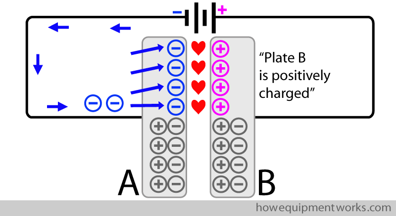
You can see that now there are free negative charges (electrons) that have been collected in plate A because they cannot cross the gap between the plates. We therefore can say that plate A is “negatively charged”.
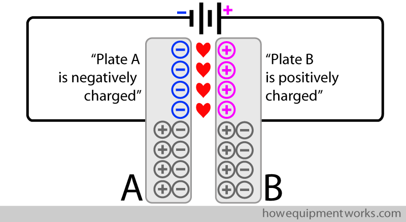
In summary, when a potential difference is applied across a capacitor, excess positive charges will form on one plate and excess negative charges will collect on the other plate. This process of making one plate positively charged and making the other plate negatively charged is called “charging the capacitor”. After a while, the capacitor has quite a lot of positive charges on one plate and negative charges (electrons) on the other plate. It is the electrical equivalent of filling the water bucket with water when you were attempting to put that fire out.
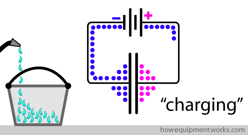
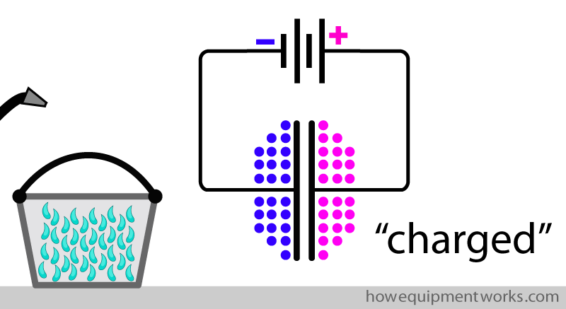
After a while, the capacitor cannot collect any more charges. We can now say that the capacitor is “charged”.
You have seen how a capacitor “collects” the current that flows into it. Now let us see how a capacitor “stores” the charges that it has collected. Let us disconnect our capacitor from the battery and see what happens. When we do this, the collected charges do not just fall out of the capacitor!
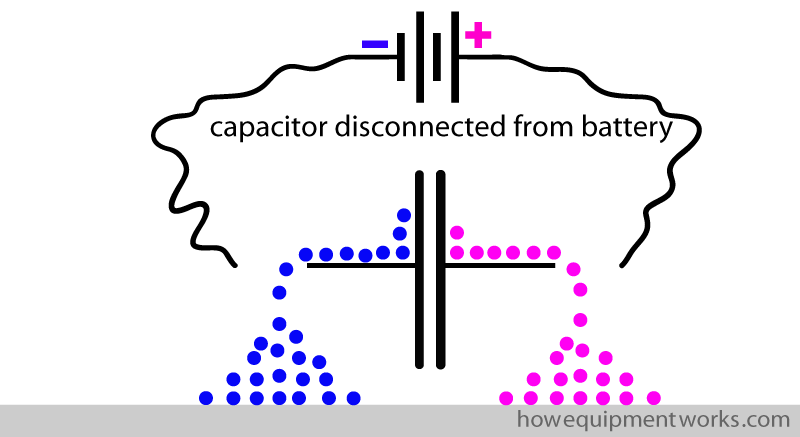
Instead, the charges just remain there. So what holds them in place?
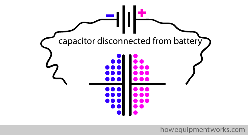
You will remember the free negative and positive charges are attracted to each other. So even though the capacitor is disconnected, this attraction across the gap between the plates keeps the charges in place. This is how the capacitor is able to “store” charges.
So far we have seen how a capacitor “stores” charge. I will now explain how we can “use” the stored charge. Shown below is a charged capacitor and a light bulb next to it. At the moment the light bulb is not connected to the capacitor. As it is not connected to anything, the light bulb does not light up.
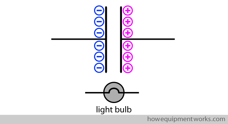
Let us connect the light bulb to the charged capacitor and see what happens. When we connect the light bulb to the capacitor, we now provide an easy pathway (shown in green) for the charges to meet each other.
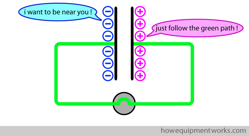
The electrons (negative charges) rush through the wires and bulb to meet the positive charges. The movement of electrons (i.e. current) through the bulb makes it light up. The process whereby the capacitor gives up its charges and makes a current flow can be called “discharging the capacitor”. When the negative charges meet the positive charges, they form couples (shown in grey).
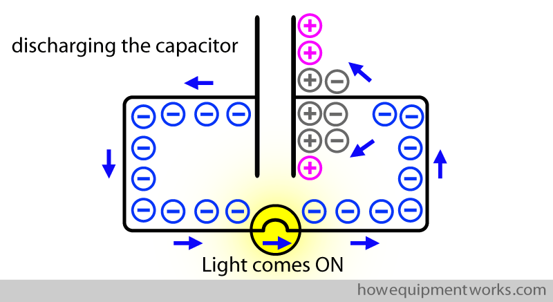
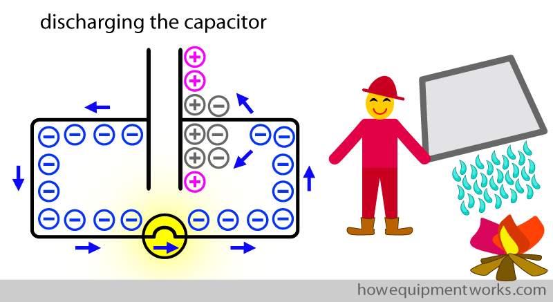
Capacitors can very quickly discharge the charges they store. This property of capacitors makes them very useful for defibrillators, where a large amount of electrons (current) needs to be sent through the heart quickly. It is like rapidly emptying the bucket to put out the fire.
Eventually, all the free negative and positive charges meet up to form couples. There are no more “free” negative charges left to move. i.e. the current stops flowing and the bulb no longer lights up. The capacitor is now said to be “discharged”.
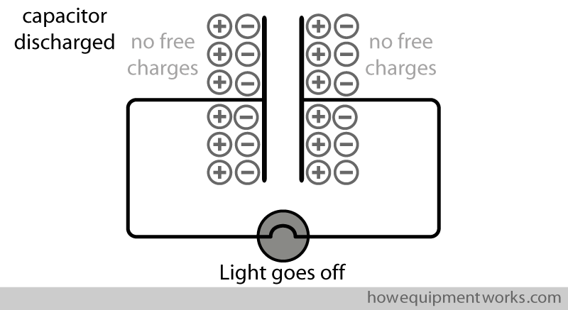
So you have seen how a capacitor (like the water bucket you used to put the fire out) can be used to collect electrons from a low-flow current, store them as a charge, and then discharge them rapidly. The capacitor in a defibrillator is used in this way and we will soon discuss these steps in more detail.
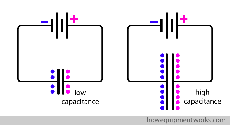
The “ability” of a capacitor to store charge is called “capacitance”. For a given potential difference, a capacitor with a “high capacitance” will store a high amount of charge whereas a capacitor with a “low capacitance” will store a low amount of charge. Because defibrillators need a very large charge to be stored, the capacitors used in defibrillators need to have a high capacitance. One way to increase the capacitance of a capacitor is to use plates with a large surface area. Shown below are two capacitors connected to the same potential difference. The capacitor on your right has plates with a larger surface area and therefore it has a higher capacitance.
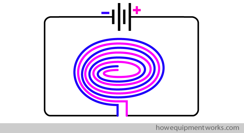
However, a capacitor with such large plates would not fit into a defibrillator. The clever engineers however have found a solution. They “roll” the capacitor into a cylindrical shape! In this way, the capacitor can have a high capacitance (because the plates have a large surface area) and still be made relatively small.
How I first learnt about capacitors!
Let me now take you to a slightly different topic, i.e. that of my childhood! When I was a child, I used to often go to local junkyards and collect various discarded electrical things to try and “repair” them.
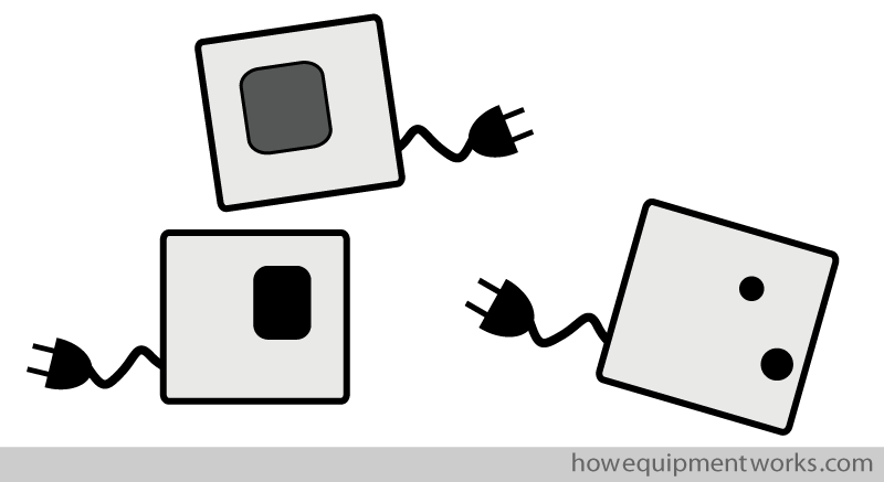
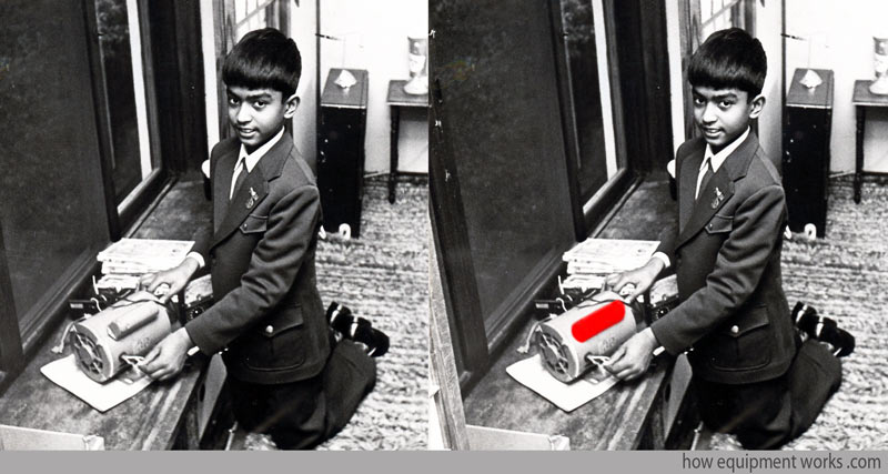
Of course, I had no real knowledge of how to repair things. And alarmingly, I used to think that since the broken electrical items were not plugged into anything, they must be “safe” to work with. In reality, many of the electronic items that I used to pick up had capacitors in them, that were occasionally fully charged. So even though they were not plugged in, I would occasionally get rather big shocks when my little fingers met capacitors!
I don’t have many pictures of my childhood, but I did manage to find this one. It shows me playing with a powerful electrical motor. I now realise, looking at the picture, that the motor had a large capacitor (highlighted in red) attached to it! I suppose I should consider myself to be lucky to be alive. My parents of course did not understand what I was up to!

Hello! My name is Pras and I am the author of this website that you are now reading. I have made this website completely free to access so that people from all over the world can benefit from it.
If you can afford it, I would be very grateful if you would consider making a single donation of one dollar (or the equivalent in your currency) to help cover the expenses needed to run this website (e.g. for special software and computers). For this website to survive, donations are desperately needed. Sadly, without donations, this website may have to be closed down.
Unfortunately, perhaps because many people think that someone else will donate, this website gets only very few donations. If you are able to, please consider making a single donation equivalent to one dollar. With support from people like you, I am sure that this educational website will continue to survive and grow.


Have you noticed cats often do mysterious things, like throwing things off shelves, staring at things endlessly, and mysteriously appearing at various places? The amusing website at the link below explains how cats are more than cute little things; instead, they control the universe using their superpowers. Visit the free website below to discover the secret world of cats.

Defibrillator circuit
Charging the capacitor
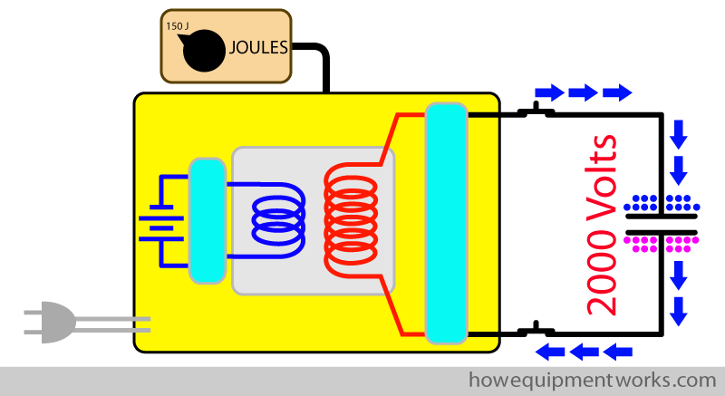
We will now, step by step, learn about the various parts of the defibrillator circuitry. As mentioned before, the capacitor plays an important part in defibrillators, as it is able to be charged using a low flow current and then is able to discharge a brief but high flow current to the heart. Let us start our discussion on the defibrillator circuitry by describing the system that charges the capacitor. When we want to use the defibrillator to defibrillate some unfortunate person, the first thing we need to do is to “charge” the capacitor. This is done by the “capacitor charging system” in the defibrillator.
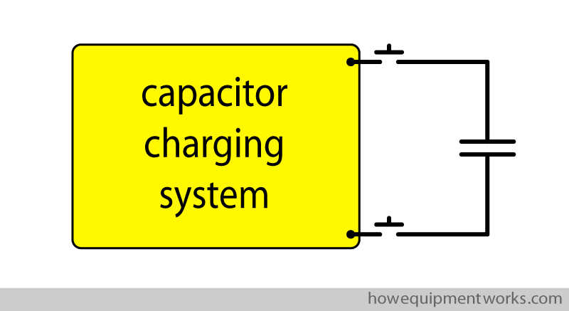
The actual workings of the charging system are somewhat complex and I do not think it is necessary for you to know it in too much detail. The charging system involves a variety of voltages and it also deals with direct current (DC) and alternating current (DC). Depending on your requirements, you may think it wise to just skim over the next section, ignoring the bits you do not understand.

The charging system needs a source of current to charge the capacitor. This can be from batteries or from the wall power socket in your hospital.
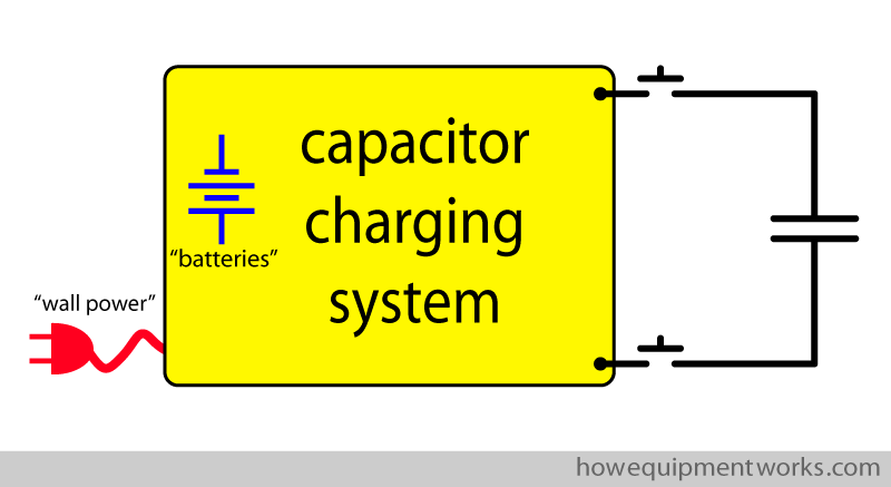
To have a charge large enough for defibrillation, the capacitor needs to be charged using a very high voltage (e.g. 2000 Volts).
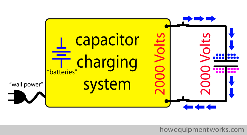
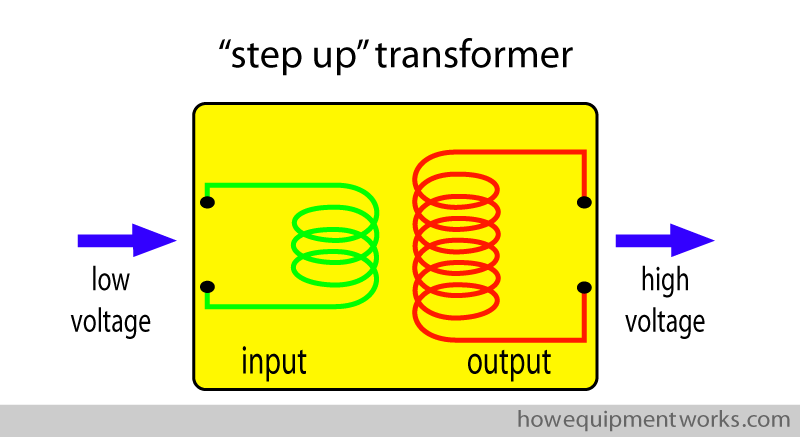
The main component of the charging system is the “step-up transformer” (which was discussed in the electricity basics section of this website). The step-up transformer is able to raise (“step up”) the voltage that comes into it.
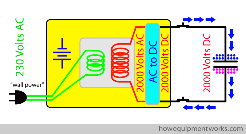
The step-up transformer in the charging system takes in current from either the batteries or the wall power source. For example, it is able to raise the supply voltage from the wall power source (e.g. AC 230 Volts) to AC 2000 Volts. However, capacitors can only be charged with a DC current, whereas step-up transformers put out current in the form of AC current. So there is a device that converts the AC current from the transformer to DC current to charge the capacitor. Please note that all these voltages and circuits that I describe are merely examples that I am using to explain things. Please do not use them to design “real-life” defibrillators!
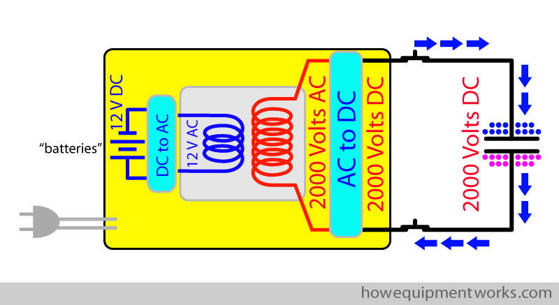
Defibrillators often need to be carried to the patient (i.e. need to be portable) so they often use batteries as a source of power. The step-up transformer is able to raise the battery voltage to charge the capacitor (e.g. from 12 V to 2000 V). However, step-up transformers need the input current to be in the form of AC current whereas batteries provide current in the form of DC current. Therefore, a special device converts the DC current from the batteries to AC before the current goes into the transformer. You will be happy to know that there are no more conversions!
The operator of the defibrillator chooses the settings on the defibrillator. The settings on currently used defibrillators do not mention things like “amount of charge” or “current” to be given to the patient. Instead, the measurement unit used in defibrillators is the “Joule”, which is a measure of “energy”. The operator chooses the energy level, in Joules, to be given to the patient.
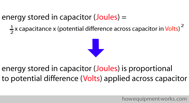
The energy, in Joules, stored in a capacitor is given by the following equation. The mathematics is a bit complicated so I have not explained the derivation of the formula. In the formula, “capacitance” is a measure of the ability of the capacitor to store a charge. For our discussion here, we will ignore it. From this equation, you can see that the energy stored by a capacitor is proportional to the voltage (potential difference) across the capacitor. The higher the voltage across the capacitor, the higher will be the charge stored in the capacitor.
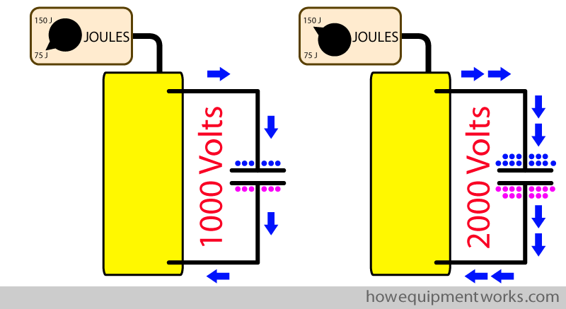
To charge the capacitor, the charging system will apply a potential difference (Volts) across the capacitor. The potential difference applied to the capacitor will be adjusted to match the energy (Joules) selected to be delivered to the patient. The higher the energy to be delivered to the patient, the higher will be the potential difference applied to the capacitor to charge it.
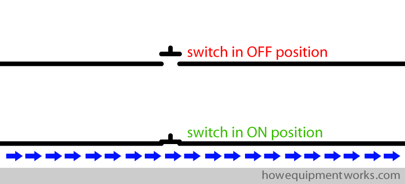
The defibrillator circuit, including the section concerning the charging of the capacitor, makes use of electrical switches. In real life, the user doesn’t directly touch these switches with their hands as the voltages involved are very high and the switches need to operate rapidly. Instead, the switches are controlled by sophisticated computers. I.e. the user controls the computer, which in turn controls the various switches. I will use the following symbols to show switches in my diagrams.
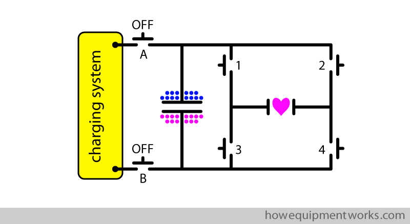
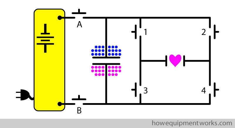
In my explanation of the defibrillation circuit, I will be using six electrical switches as shown in the diagram below. For now, we need to only worry about the charging part of the circuit (shown in green box).
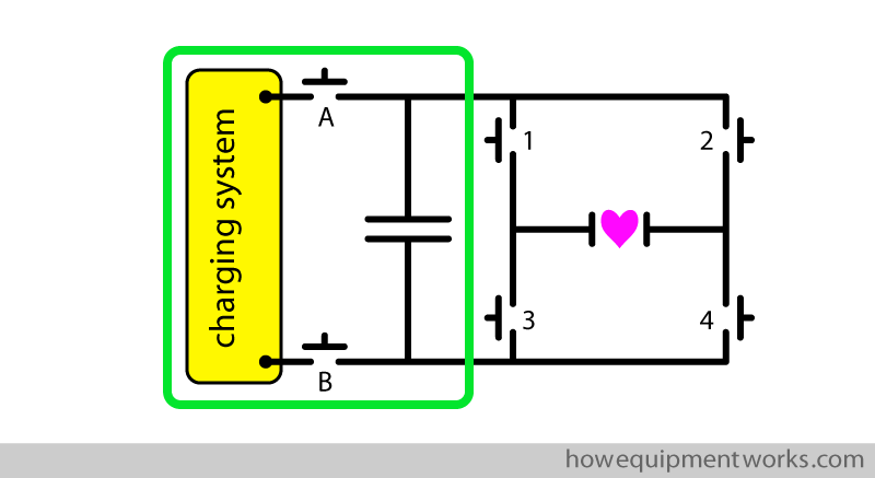
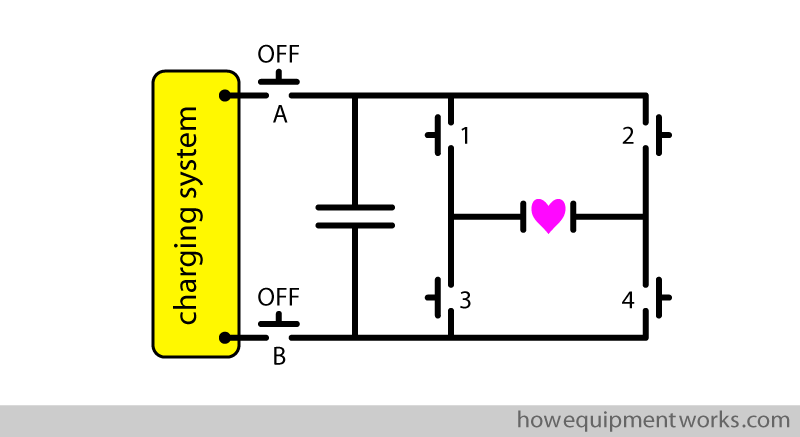
The charging system is connected to the capacitor via two charging switches (A and B). When the capacitor is not being charged, both these switches are in the “OFF” position.
To charge the capacitor, charging switches A and B are put into the “ON” position and the charging system applies a high voltage across the capacitor. As discussed before, the magnitude of the voltage applied is based on the energy level selected by the operator. The higher the energy level selected, the higher will be the voltage needed to be applied across the capacitor.
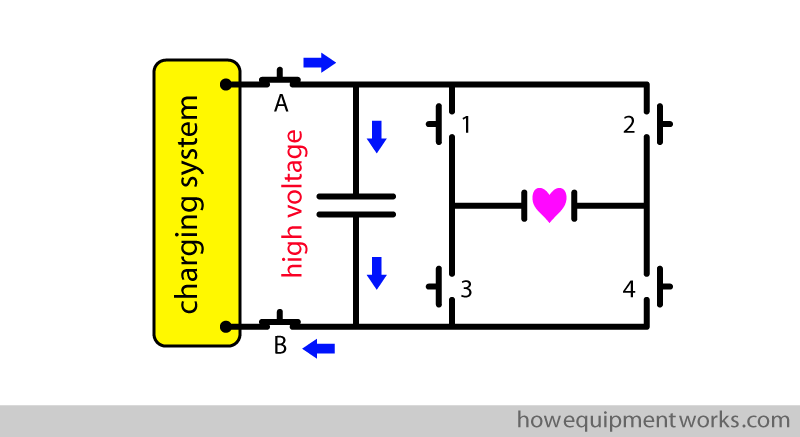
Current from the charging system flows into the capacitor and the capacitor starts to get excess positive charges in one plate and excess negative charges in the other plate. The charging system monitors the charging process.
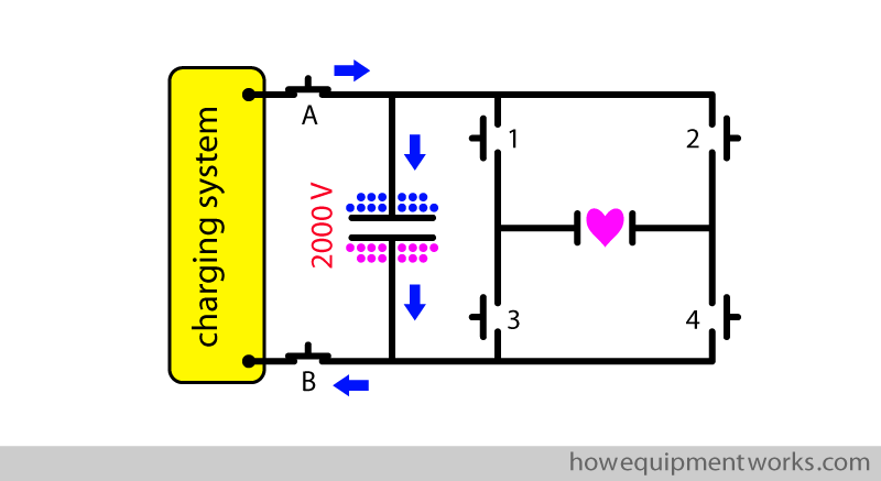
Once the capacitor has adequate charge appropriate for the needed defibrillation energy, the charging switches (A and B) are put to the “OFF” position to stop further charging. The charging process is now complete and at this point, medical personnel will often say something like “defibrillator charged”. It is a warning to everyone that soon the discharge will happen.
Discharge part of the defibrillator circuit
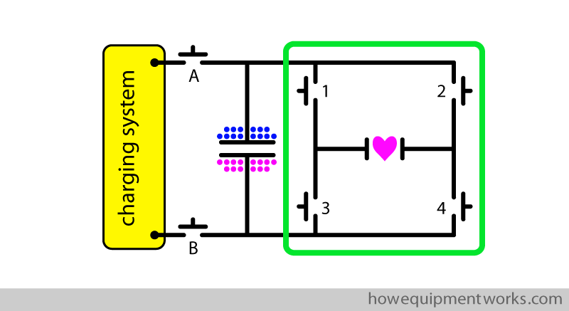
The capacitor is charged and is now ready for discharge into the patient. In the diagram below, the “discharge part” of the defibrillator circuit is shown in the green box. You will notice that there are four switches (1,2,3,4) in this area. These switches will, later, connect the heart to the capacitor. However, at present, these four switches are “OFF” and therefore the charged capacitor is not connected to the heart. The capacitor, at this point, is simply storing the charge.
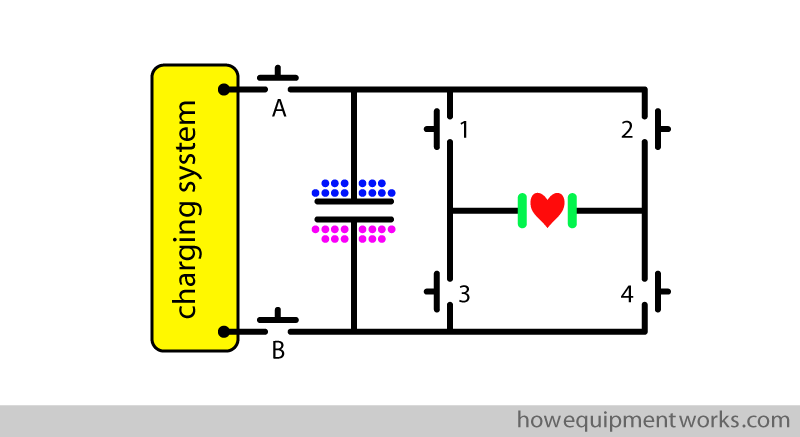
In my diagrams, the heart is of course drawn only as a symbol. The circuit connects to the heart via two pads (shown in green).
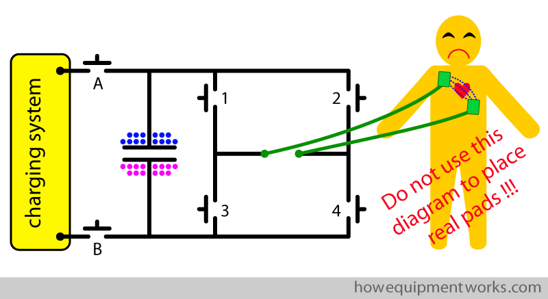
Of course, the real human heart is very different to the ones I have drawn in my diagrams. In actual use, the defibrillation current is applied to two areas of skin on the chest of the patient using special “conductive pads”. The current goes from the defibrillator to the patient and returns from the patient to the defibrillator via wires connected to the chest pads. The current goes from one pad to another, passing a variety of structures such as skin and of course the heart. By the way, please do not use my rough diagrams to guide where you actually place pads in a real patient!
Use of oscilloscope to see waveforms
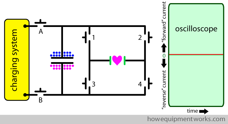
During defibrillation, the current that goes through the heart changes over time. To study the flow of current over a period of time, one needs a device called an “oscilloscope”. An oscilloscope has a screen which has two axes as shown below. The horizontal axis shows time and the vertical axis shows the quantity we are measuring, which in the case of the defibrillation, is “current”. The oscilloscope is able to plot a graph of current over time and it will be very useful in our discussions ahead. The oscilloscope below has been connected to the defibrillator output. At the moment, the capacitor is not connected to the heart (i.e. switches 1,2,3,4 are all “OFF”) and therefore no current is flowing through the heart. The oscilloscope shows this as a flat trace (red line shown below) since the current flow over time is zero.
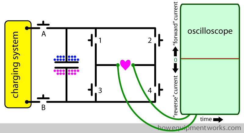
To make my diagrams less cluttered, I won’t be showing the wires between the heart and oscilloscope anymore.
The tracing on an oscilloscope showing the defibrillation current over time can be called the “waveform”.
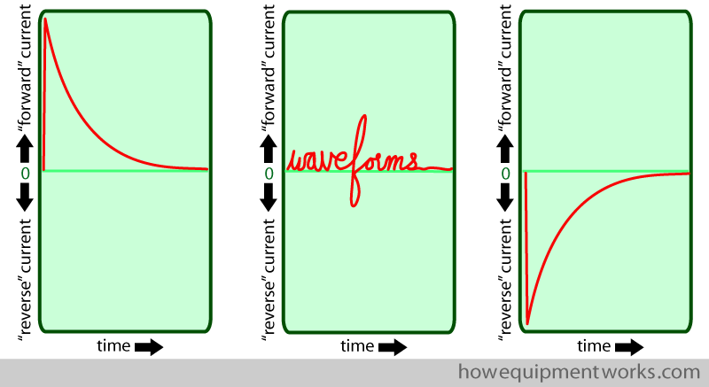
Basic discharge waveform of a capacitor
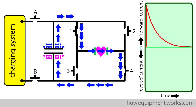
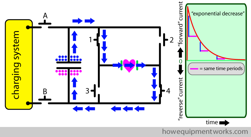
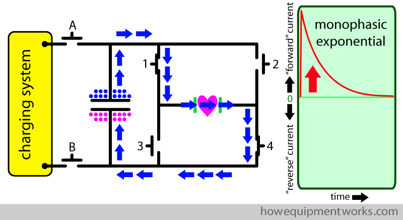
As you may recall, for the capacitor to discharge, the electrons (negative charges) need a path to flow from one plate of the capacitor to the other plate of the capacitor. We can create this pathway by switching “ON” switches 1 and 4. The capacitor now discharges via the pathway shown by the blue arrows. The oscilloscope waveform shows that initially, the discharge current flow is high and that it then decreases over time. This is a typical waveform seen during the discharge of a capacitor.
Let us look at the waveform in more detail. When a capacitor discharges, the current flow over time decreases in what is called an “exponential” way. When a current decreases in an exponential way, the rate of the decrease (i.e. how much current decreases over a given time period) is proportional to the current flow at that time. The oscilloscope below demonstrates the exponential decrease of the current from the capacitor. The pink horizontal bars represent equal time periods. You can see that for these same time periods (pink bars), the rate of decrease (vertical blue lines) decreases over time. When the current flow was high (i.e. at the start of the graph) the rate of decrease was high (tall blue line), whereas when the current flow was low(i.e. towards the end of the graph), the rate of decrease was low (short blue line). Unfortunately, it is beyond the scope of this website to explain “exponential” decreases in more detail. If you are interested (it is an important concept in engineering and medicine), there is plenty of material online regarding it (type the words “exponential decay” into Google).
“Monophasic” waveform
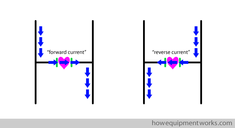
I will soon explain to you what a “monophasic” waveform is. The word monophasic relates to the “direction” of current flow. As you see below, at a given moment, the current can travel in one of two directions through the heart. I will call current that goes from your left to your right as “forward current”. And similarly, I will call current that goes the other way, “reverse current”.
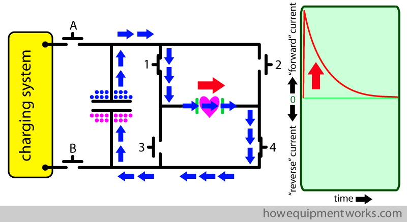
The oscilloscope can, in addition to showing us the magnitude of current flow over time, also show the “direction” of current flow over time. In the example below, you can see that the current flow is “forwards”. In our oscilloscope, the “forward” current flow is shown by the waveform going upwards.
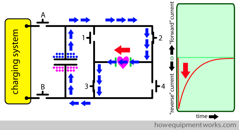
Let me now show you how the oscilloscope waveform looks when the current is made to go through the heart in the reverse direction. We can make the current go in the reverse direction by discharging the capacitor through different switches to those that we used before. This time we put “ON” switches 2 and 3. As you can see below, this makes the current flow in the reverse direction. The oscilloscope shows this reverse direction current by displaying the waveform of current in the opposite direction to before (i.e. the waveform goes below the baseline).
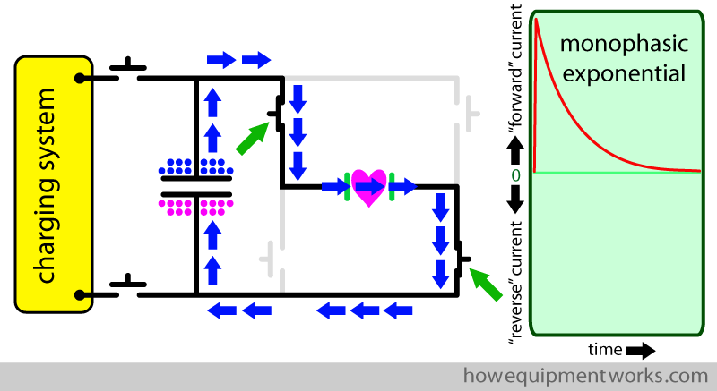
Let us return to our first example, where we put switches 1 and 4 “ON”, making the current go in the “forward” direction. As you saw before, this makes the oscilloscope show an exponential waveform, which as the capacitor discharges, returns to the baseline (zero). Please note that the waveform in the oscilloscope has never gone below the baseline. This tells us that, in our example, the discharge current only went in “one direction” (i.e. forwards). A waveform showing current flowing in only one direction is called a “monophasic waveform” (“mono” means one and “phasic” sort of means “direction”).
As you know, the capacitor discharge waveform is “exponential”. So, combining monophasic and exponential, this kind of waveform is called a “monophasic exponential” waveform.
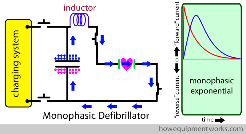
The monophasic defibrillators also had a large component called an “inductor”, a large coil of wire (shown in blue below) placed in the circuit. The inductor “slows” the current, making it have a lower peak and “spreading” it over a longer time (see blue waveform). These effects were considered good for clinical reasons. The physics concerning how inductors work is a bit complex, and I therefore won’t explain it here. Also, in newer defibrillators, called biphasic defibrillators, which I will explain soon, the inductor is no longer used.
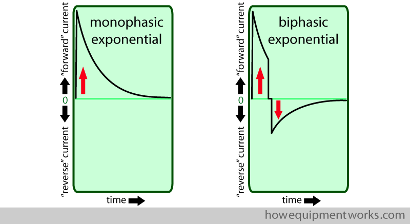
In the past (before around 25 years ago), defibrillators were designed to produce monophasic exponential waveforms as has been explained so far. However, since then, it has been found that a different type of waveform is more effective at successfully defibrillating hearts. The newer waveforms are called “biphasic waveforms”, which essentially means that during defibrillation, the current first goes in the forward direction and then changes direction and goes in the reverse direction. An example of a biphasic waveform is shown below. I will explain to you soon about how biphasic waveforms are delivered.
I do need to give a warning to the many anaesthetists (medical personnel who put patients to sleep for surgical operations) visiting this website. Unfortunately, there may be some anaesthesia textbooks and other learning resources which only explain the old monophasic defibrillators instead of the newer biphasic defibrillators. If you come across such, please contact the author and gently suggest that it be updated. Similarly, some examination bodies may have not updated their “question bank” to include biphasic defibrillators. If you can, please try and check with them.
Biphasic defibrillator
Let us now learn about how the modern biphasic defibrillator works. The old monophasic defibrillators, you have so far read about, had only two discharge switches (green arrows). The biphasic defibrillator circuit just has some additional wires and switches (shown in grey below). I will of course explain it to you soon.
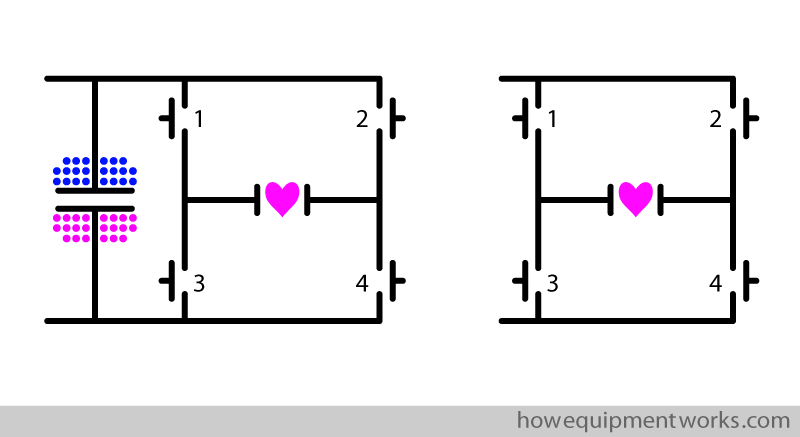
The charging system of the biphasic defibrillator is very similar to the monophasic defibrillator, so I won’t repeat how it works here.
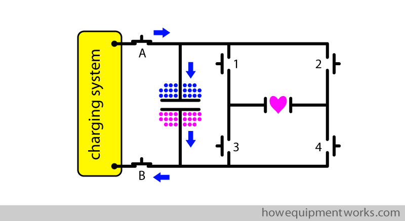
To simplify things and to make room for clearer diagrams, at times I will not show you the charging part of the circuit at all. If space is very tight, I may even omit showing the capacitor. So even when not shown, please always assume that there is a correctly charged capacitor. Also note that unlike the monophasic defibrillator, which had two switches, the biphasic defibrillator has 4 switches, which I have numbered. When describing how these switches function, I will refer to these numbers.
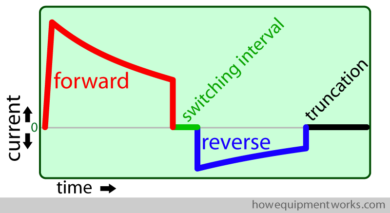
We are now ready to learn how the biphasic waveform is created in modern defibrillators. In the image below, I have enlarged the biphasic waveform. To simplify my explanations to you, I have divided it into four parts and, as shown below, have given each part of the waveform a name. The waveform may look complicated to some of you, but please do not worry. Once you understand it, you will be able to draw it easily. In the next sections, I will explain to you how each segment of the waveform is created by the defibrillator.
Forward current part of the biphasic waveform
The biphasic defibrillator starts by sending current through the heart in the “forward” direction. This is done in a similar way to how the monophasic defibrillator delivers current to the heart. i.e. switches 1 and 4 are put “ON”. However, there is a crucial difference. In the case of the biphasic defibrillator, these two switches are switched “OFF” before the capacitor has finished discharging. When these switches are switched “OFF”, the current flow to the heart stops and the oscilloscope tracing returns to the baseline (zero). However, the capacitor still has some charge left in it, as was prevented from emptying completely.
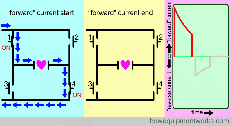
“Reverse current”
As you saw previously, the forward current was stopped by switching “OFF” switches 1 and 4. The biphasic defibrillator now needs to “reverse” the direction of the current flow to the heart. It does this by switching “ON” switches 2 and 3, which as you can see below, makes the current go in the reverse direction in the heart. The oscilloscope shows the reverse current by making the graph go below the baseline.
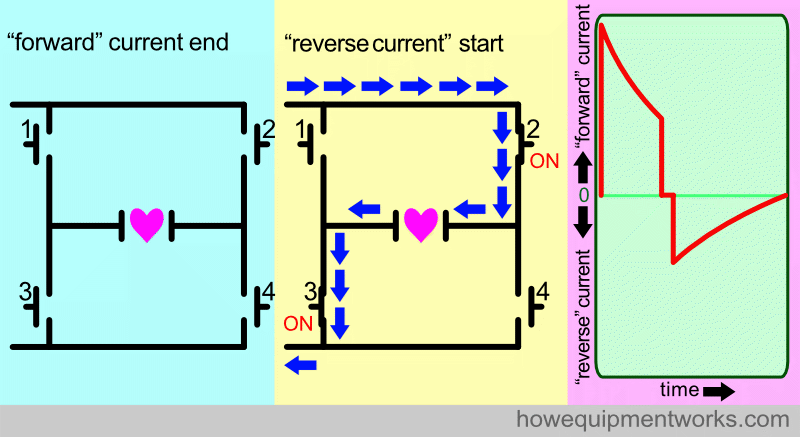
However, if you look carefully, you will see that there is a brief period between the forward current and reverse current, where the oscilloscope graph shows no current flow. In the magnified oscilloscope graph shown below, you can see this brief period as a short red line on the baseline (zero). I call this time period the “switching interval” and will explain to you why it is there.
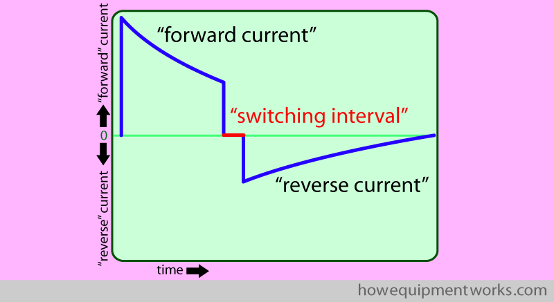
The switching interval starts when the “forward current” switches (1 and 4) are switched “OFF” and ends when the “reverse current” switches (2 and 3) are switched “ON”. During the switching interval”, all four switches are in the “OFF” position. The “switching interval” is something that has been deliberately added by the designers of defibrillators. The switching interval provides adequate time for the “forward” current switches (1 & 4) to first “properly” switch “OFF” before the “reverse” current switches (2 & 3) are put “ON”.
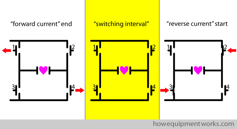
In defibrillators, the switches are electronically controlled and operate at very high speeds. Therefore they need only a brief “switching interval” between the end of the forward current and the start of the reverse current. That is why you only see a brief “switching interval” on the oscilloscope (green arrow and short red line).
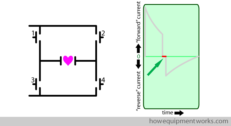
Let us now return our attention to the “reverse current”. As you saw before, to give the heart the “reverse current”, switches 2 and 3 are switched “ON”. The reverse current makes the oscilloscope graph go below the baseline (red arrow).
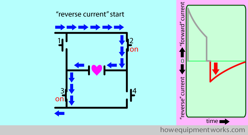
In the diagram below, I have named the end of the reverse current as the “reverse current natural end”. What I mean is, this is how the waveform would look like if we let the capacitor completely discharge into the heart, without us doing anything more to the switches. In this situation, as demonstrated below, the waveform shows that the reverse current gradually decreases and eventually becomes zero. As I will explain later, in real life, we manipulate the switches and prevent the reverse current from ending in a “natural” way.
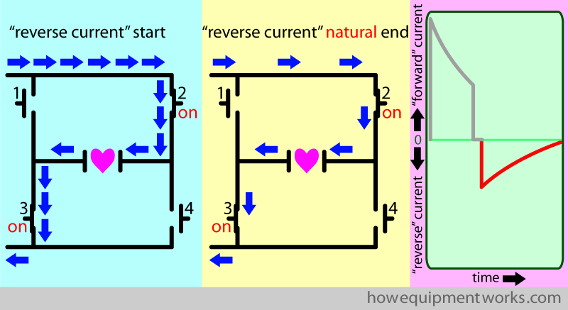
“Truncation”
As mentioned before, if we don’t change any switches, the “reverse current” returns to the baseline “gradually” (see red arrows). Unfortunately, as I will explain to you, this “gradual” decrease at the end of the waveform is problematic.
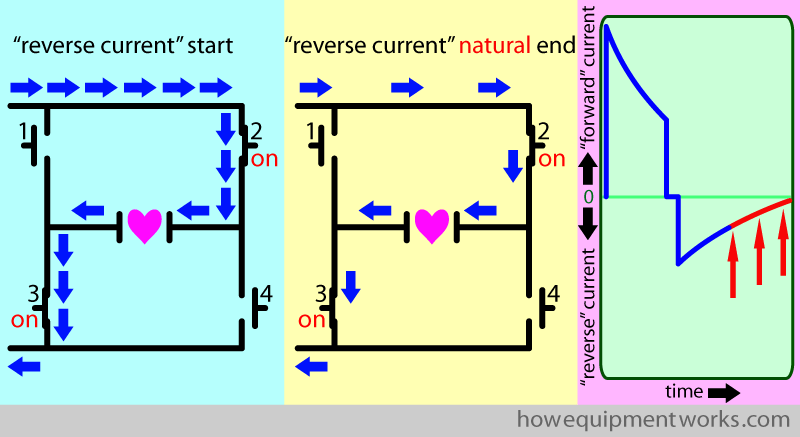
You will remember from our discussion on the basics of defibrillation that the defibrillation current needs to be large to be effective.
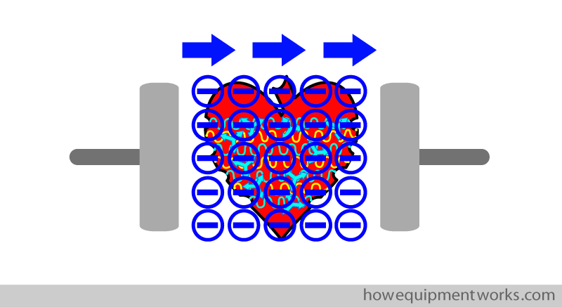
Conversely, if a small current is used in defibrillation, a rather dangerous effect may occur. A small current may actually cause fibrillation in the heart! The mechanism of how this happens is unfortunately beyond the scope of this website.
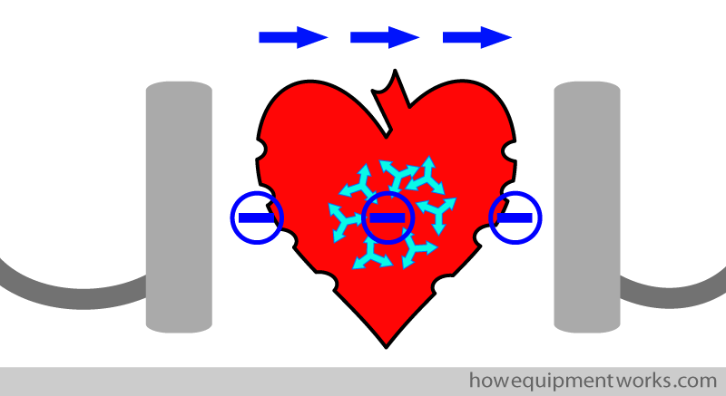
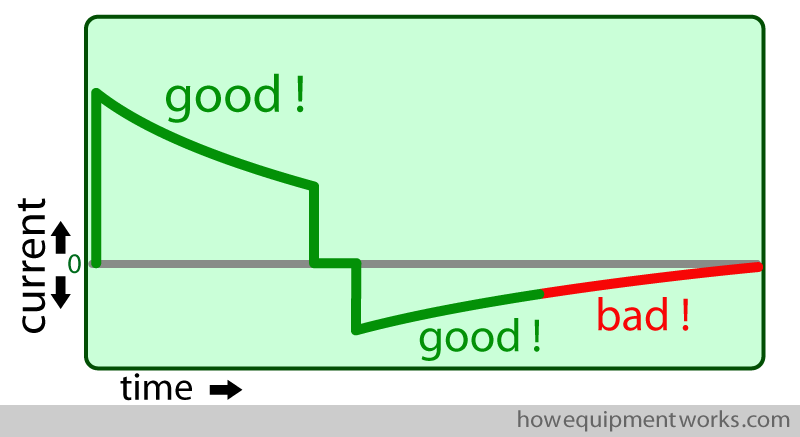
So, from a defibrillation point of view, we need to use reasonably large currents to have effective defibrillation and we also need to avoid small currents that can cause fibrillation. Keeping these in mind, let us look at the biphasic waveform. You can see in the example below, that the “forward current” and most of the “reverse current” is large and therefore good for defibrillation. However, the tail end (shown in red) of the “reverse current” is small and as discussed, has the potential to fibrillate the heart. i.e. the low current at the tail end of the waveform has the potential to cause fibrillation in the heart that has just been defibrillated by the earlier high current part of the waveform. Therefore, the defibrillator needs to avoid giving a low current tail to the patient.
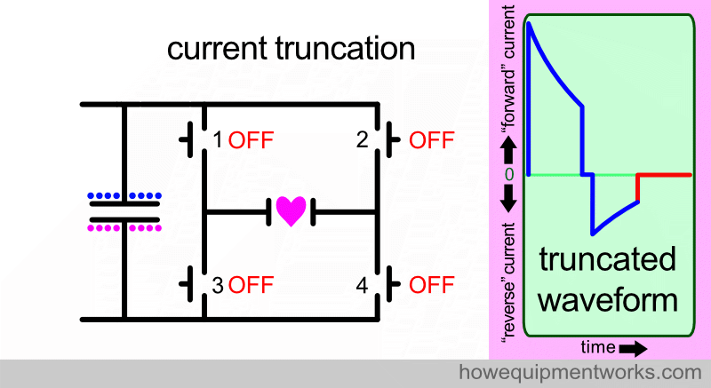
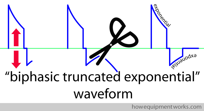
To avoid the problem we discussed, the defibrillator “cuts off” the harmful tail end of the biphasic waveform. The “official” term used to describe this “cutting” is called “truncation”. Once the waveform tail end is cut, it is called a “truncated waveform”. I will next explain how the waveform truncation done.
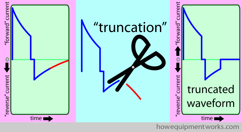
The way the defibrillators truncate the reverse current in real life is very complex. I think a fair simplification is to imagine that the truncation happens by all four switches switching to the off position. This abruptly stops the current flowing into the patient.
Summary of biphasic defibrillator sequence
Let us at this point summarise the sequence of events that happen when we use the biphasic defibrillator:
- To provide the necessary large current for defibrillation, we need to charge the capacitor. The charging system can use battery current or current from a wall socket. Charging switches A and B are switched “ON” and the capacitor is charged using a high-voltage DC current. Once charged to the required level, switches A and B are switched “OFF”.
- For the “forward current”, switches 1 and 4 are switched “ON”, and then switched off.
- There is a brief “switching interval” where all switches are “OFF”.
- The “reverse current” is started by switching “ON” switches 2 and 3.
- The “reverse current” is then stopped (truncated) by switching all switches OFF.
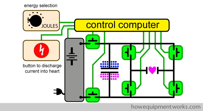
In real life, the charging system and the internal switches of the defibrillator are electronically controlled by a computer. The user selects the required energy and the computer controls the charging system to charge the capacitor. When appropriate, the user presses the button to deliver the current to the patient. The computer then controls the four high-speed electronic switches to deliver the biphasic defibrillation current.
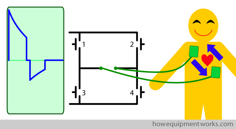
Throughout our discussion, we have “seen” the current flow as a biphasic waveform on an oscilloscope. However, keep in mind that in real life, the defibrillation current flows via pads placed on the patient’s chest. The biphasic current goes through the heart first in one direction and then changes direction to go the other way. (Also in real life, the patient wouldn’t be smiling as shown in the image below!)
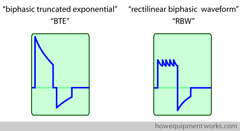
By the way, the biphasic waveform that we have so far studied is “officially” called “biphasic truncated exponential” waveform, often the name being shortened to “BTE” waveform.
The biphasic truncated exponential (BTE) waveform is not the only waveform that is currently in use. There are other biphasic waveforms, such as one called “Rectilinear Biphasic Waveform” (RBW), which I have shown below. Unfortunately, it is beyond the scope of this website to discuss which waveform is medically more effective at defibrillating the heart. You can get information about various waveforms elsewhere on the internet.
Automated External Defibrillator (AED)
The success of defibrillation is highly dependent on how soon after fibrillation the defibrillation current is given. Literally, every second counts.
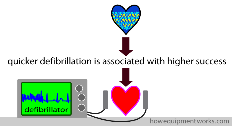
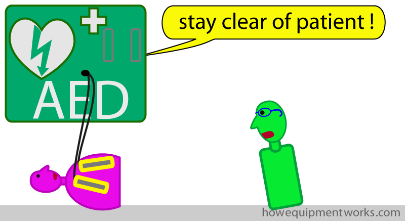
In the past, if someone had ventricular fibrillation in a non-hospital setting, there was a considerable delay before an ambulance with trained medical personnel and a defibrillator would arrive. To reduce the delay before defibrillation, there is a move to place defibrillators in public places, workplaces, schools, etc. Such defibrillators are specially designed to be easy to use by the public and are called “public access defibrillators”. They are also called “automatic external defibrillators” (AED).
If someone is suspected of having ventricular fibrillation (i.e. cardiac arrest), a member of the public can take a nearby public access defibrillator and follow its instructions. The defibrillator comes with two pads attached to wires. The instructions will show where to stick the two pads onto the patient. The AED, using an electronic voice, will also guide the members of the public about what to do.
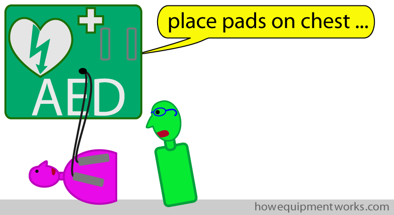
Once connected to the patient, the AED analyses the heart rhythm (it is a very clever piece of equipment) and delivers a defibrillation current if it detects that the patient has ventricular fibrillation. I cannot go into details of the various AED devices, but you can see plenty of videos on the internet showing how they are used. Also, please find out, in places where you visit often, where the AEDs are located. Someday, that information may save someone’s life!
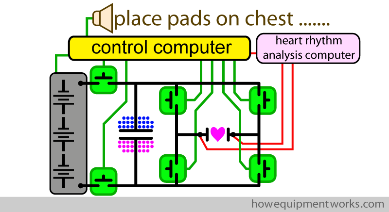
The basic design of the AED is very similar to the circuits we have discussed so far. However, there are design differences between AEDs and hospital-based defibrillators and it is beyond the scope of this website to discuss them in detail. For example, AEDs have computer systems to analyse and diagnose ventricular fibrillation. They also need circuits to produce the “voice” that guides the members of the public in helping the patient. As the AEDs may be placed in all sorts of places, they often rely on long-lasting batteries and need to be made quite physically strong.
Implantable Cardioverter Device (ICD)
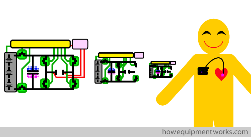
Finally, I would like to briefly mention that there are devices called “implantable cardioverter devices”, more commonly known as “ICDs”. These are essentially like the AEDs we just talked about, except that the device is made extremely compact. Some people have heart conditions that make them more likely to get ventricular fibrillation and other life-threatening rhythm problems in their hearts. In these patients, one option is to place an ICD inside the body and permanently connect it to the heart. The ICD continuously analyses the heart rhythm and delivers a defibrillation current when necessary. Needless to say, putting all that circuitry into something so tiny is an engineering miracle.
We have now reached the end of our discussion on how defibrillators work. I hope you have enjoyed it and please remember to tell your colleagues to visit this website! Thank you and goodbye.

Hello! My name is Pras and I am the author of this website that you are now reading. I have made this website completely free to access so that people from all over the world can benefit from it.
If you can afford it, I would be very grateful if you would consider making a single donation of one dollar (or the equivalent in your currency) to help cover the expenses needed to run this website (e.g. for special software and computers). For this website to survive, donations are desperately needed. Sadly, without donations, this website may have to be closed down.
Unfortunately, perhaps because many people think that someone else will donate, this website gets only very few donations. If you are able to, please consider making a single donation equivalent to one dollar. With support from people like you, I am sure that this educational website will continue to survive and grow.

