Note: This is part 3 of the discussion of electrical safety. If you have not read part 1, please click here to go to part 1.
How the wire from equipment case to Mother Earth protects you
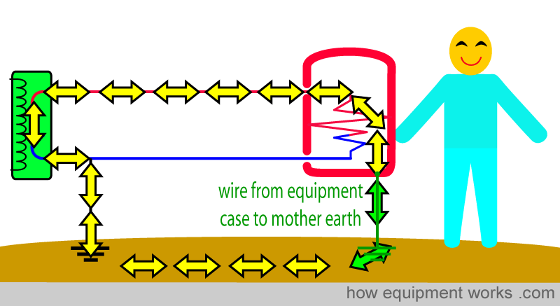
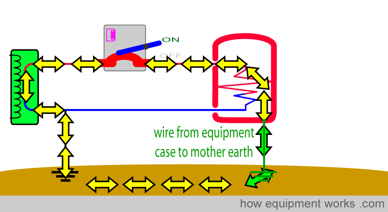
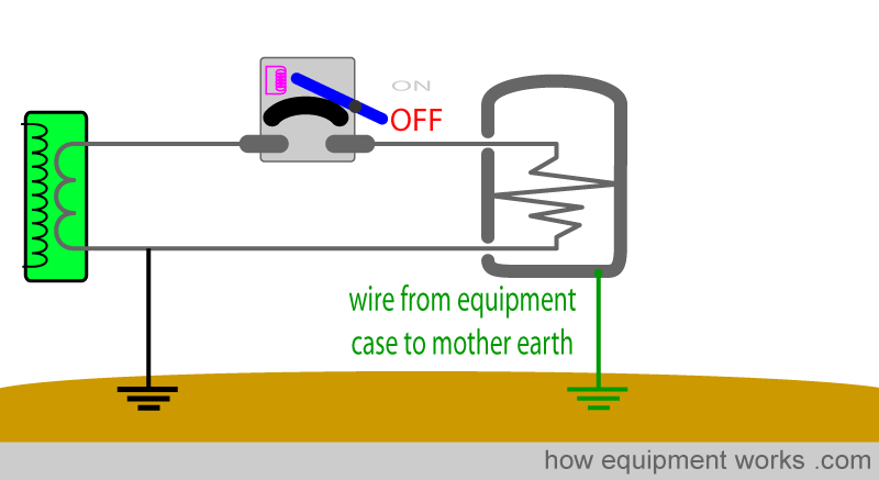
There is an additional wire that we can add to the electrical wiring we have studied so far to make things safer. This is a wire that is used for equipment that has metal surfaces. This wire, which I shall call, “wire from equipment case to mother earth”, as shown below, is connected from the metal casing of our equipment (e.g. electric kettle) to mother earth. This wire I have shown in green below.
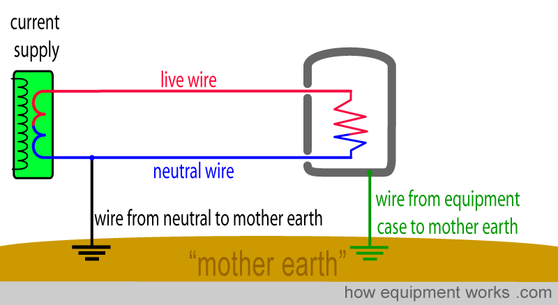
At this point, make sure that you don’t get confused between the two wires that go to Mother Earth.
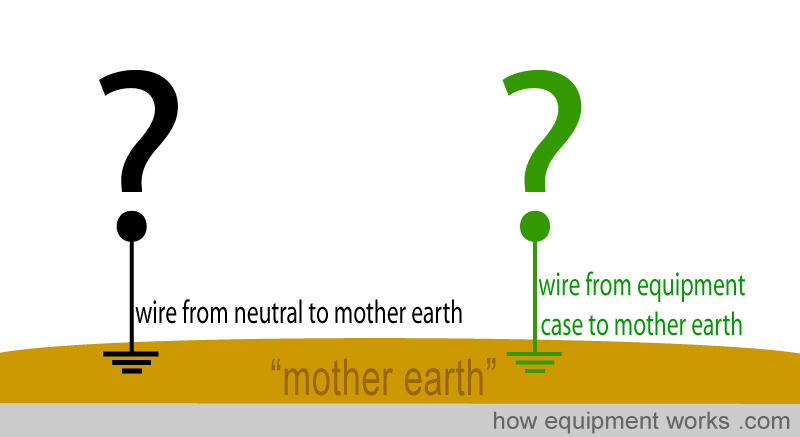
Both the wires go to Mother Earth. However, one connects to the neutral wire (black arrow) and the other connects to the metal case of the equipment (green arrow).
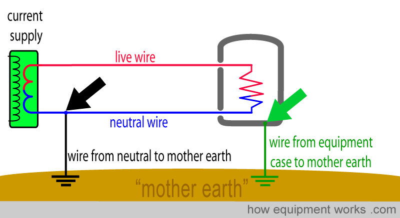
Also, the wire from neutral to Mother Earth is usually some distance from you. On the other hand, the wire from the equipment case to Mother Earth is quite near you, as it is connected to the equipment you are using.
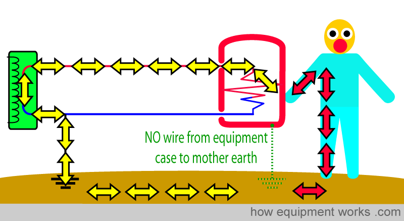
The wire from the equipment case to Mother Earth protects us in two ways as will be explained to you soon. Let us now make our equipment faulty. The current wire inside the device has now touched the case (pink arrows) and the metal case is now full of current. If you touched it, you would get a shock.
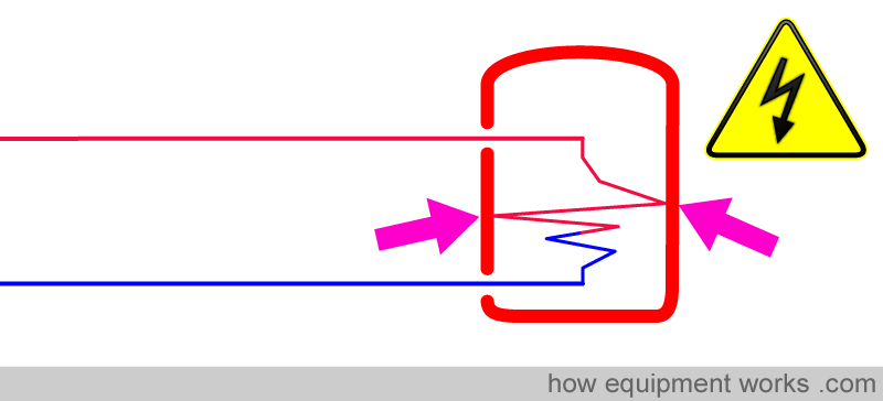
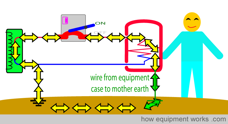
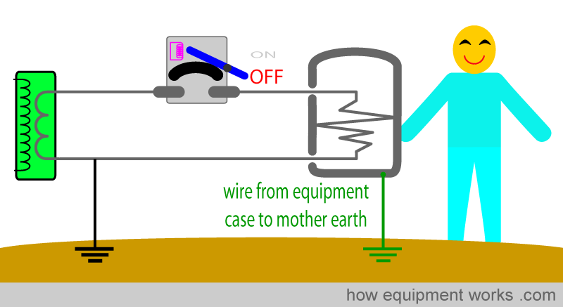
First, let us assume that there is no wire from the equipment case to Mother Earth. As we have discussed before, the current chooses to go through the man, giving him a shock.
Now let us take the same scenario, but this time we have the wire from the equipment case to Mother Earth connected. Now the current has a choice of two paths to take to reach Mother Earth. It can either go through the man (red arrows) or go through the wire from the equipment case to Mother Earth (green arrows).
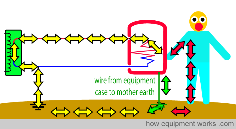
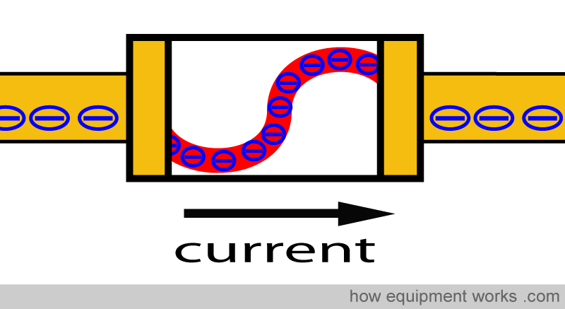
So which path will the current take? One thing about electric current is that like humans, it will try and take the easiest path. As a human, if there are two paths to the same destination, I am sure you will take the one that involves the least effort (blue road below).

Current also likes to take the easiest path. For current, the easiest path is the path with the least resistance. The current has to “decide” if the man or the wire from the equipment case to Mother Earth has the lower resistance.
Now which of the two paths has the lower resistance? Wires are extremely good conductors of electricity and therefore carry current easily. Hence, the wire from the equipment case to Mother Earth has the lowest resistance. Humans, especially with their “dry skin”, are relatively poor conductors and have a high resistance.
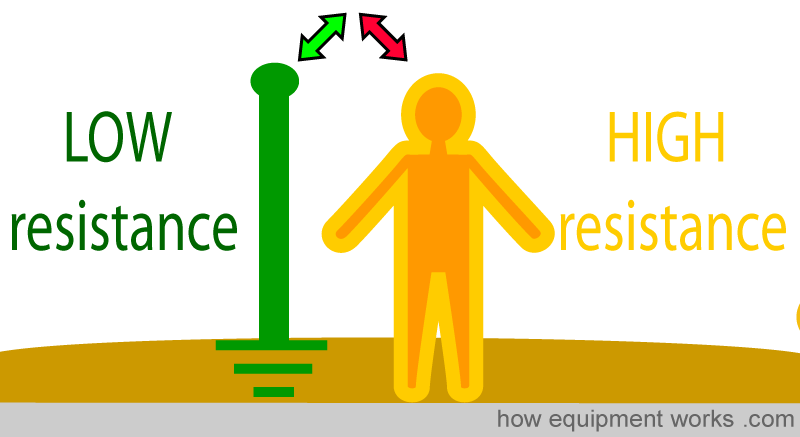
Since the equipment case to Mother Earth wire has a much lower resistance to current flow than the man, the shock current goes through the wire, instead of the man. In this way, by providing an easier path for the current, the equipment case to Mother Earth wire “diverts ” the shock current away from the man.
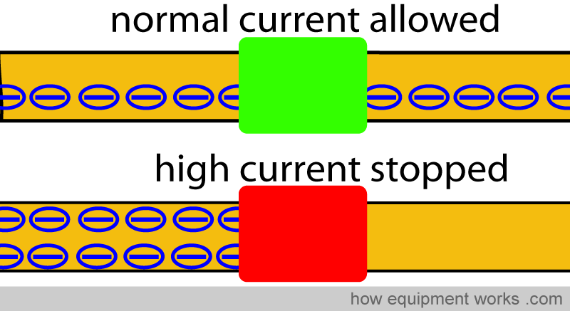
However, this is not the only way the ‘wire from equipment case to mother earth’ prevents shock. Not only does it divert the shock current, it also stops its flow. However, it cannot stop the current flow on its own. Instead, it needs the help of another category of safety devices which for now I will call “high current stopping ” devices. These devices are designed to stop the flow of current when the current through them exceeds a set safe amount. I will first explain what these devices are and then explain how they work along with the ‘wire from equipment case to mother earth’ to stop the flow of current.

Do you work in the anaesthetic team? If you do, please visit the free website below, which has anaesthesia-related fun and safety material. Click the button below to visit.

There are two main types of “high current stopping ” devices:
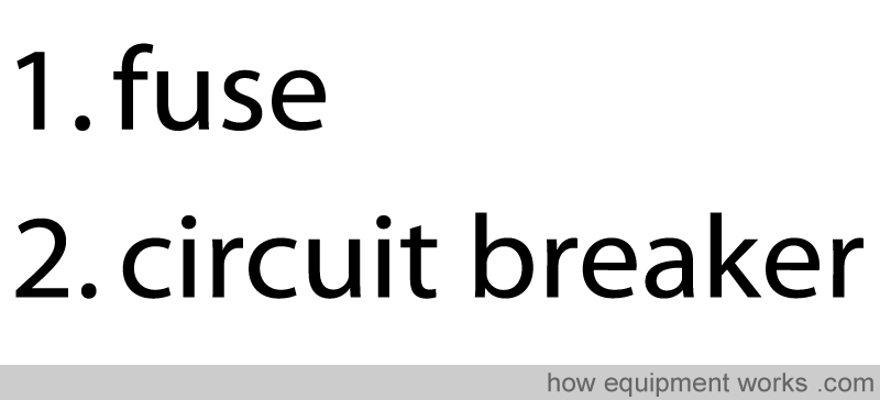
Fuses:
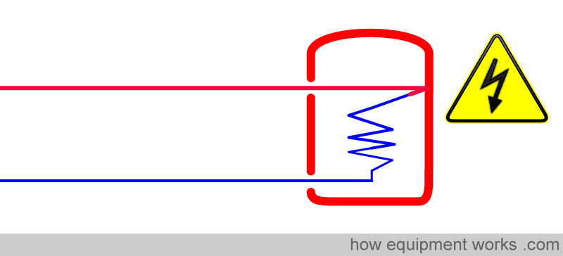
These devices consist of a short length of wire that can easily melt. This wire (red, below) is usually enclosed in a protective cover. The current flows through the device.
If there is an excessively high current, the wire inside the fuse heats up and melts. The melted wire in the fuse can no longer carry current, thereby stopping the high current flow.
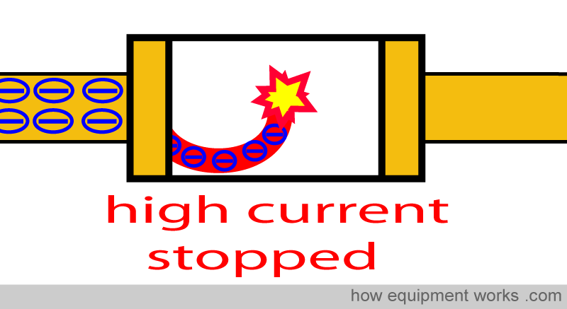
Once the fault that caused the problem is rectified, a new fuse must be installed. I.e. these are “single-use” devices. Fuses are not very expensive to buy, but replacing them is not that convenient.
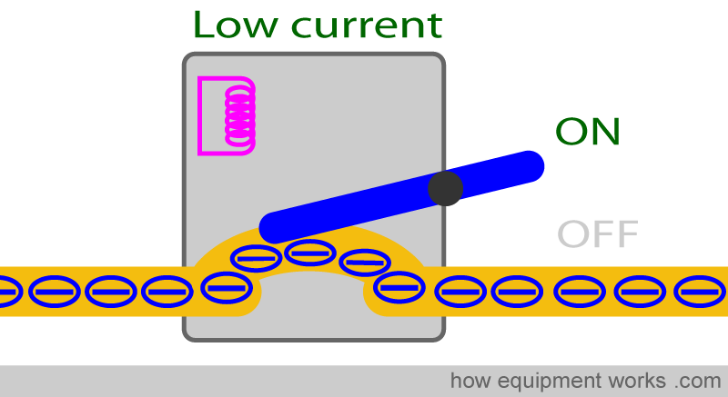
Circuit breakers:
These are more convenient than fuses since they don’t have to be replaced each time they function. Like a fuse, the circuit breaker “breaks ” (stops) the current flow if the current flow exceeds a set limit.
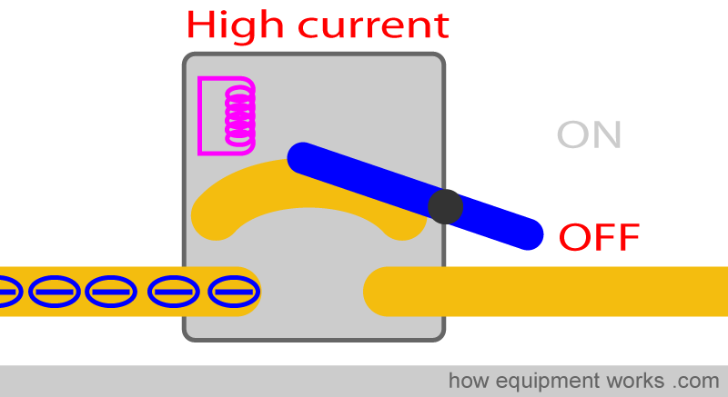
Once the high current problem is solved, the switch can easily be pushed into the ON position and the current will flow again. Therefore, unlike a fuse, nothing needs to be replaced.
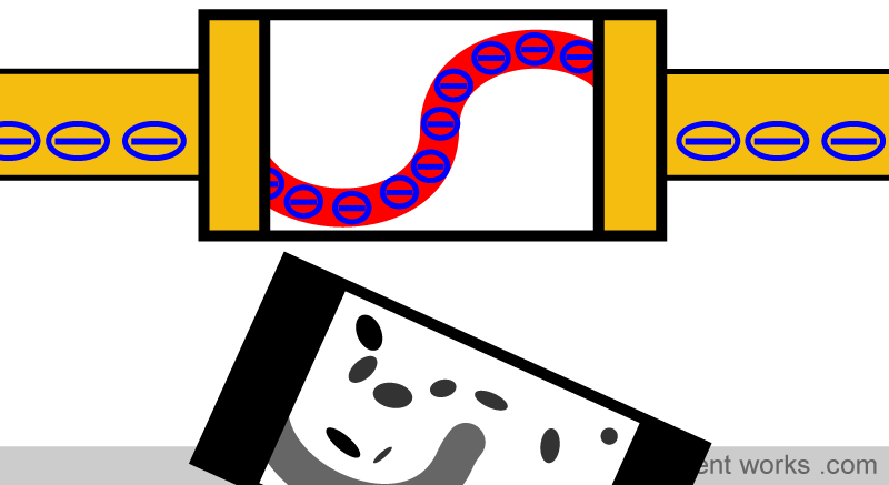
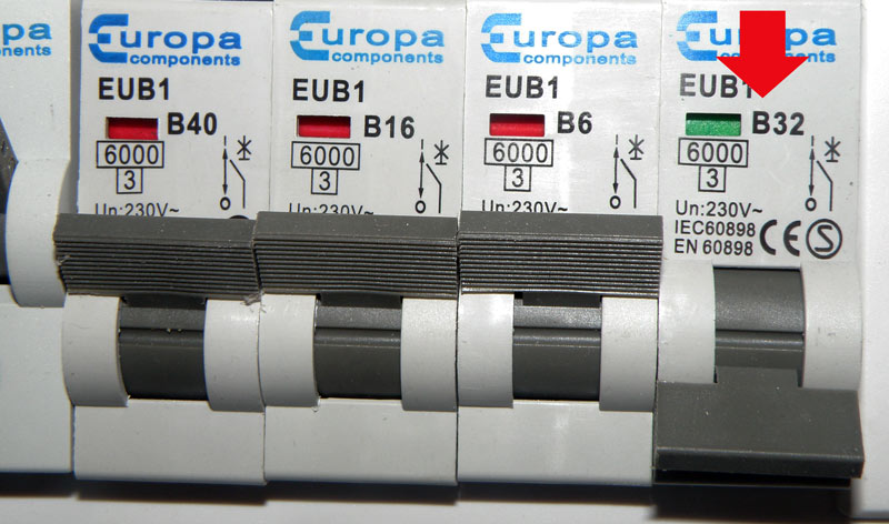
Circuit breakers are also called “trip switches ” . Have a look at your home today. You may have a fuses or circuit breakers. Below is a picture of the circuit breakers in my house. The one with the red arrow has “tripped” into the off position.
These “high current stopping ” devices work together “as a team” with the “wire from the equipment case to Mother Earth”. Let me explain.
Under normal conditions without a fault, a normal current is going to the equipment. The current goes through the circuit breaker which, because the current is not high, remains in the ON position.
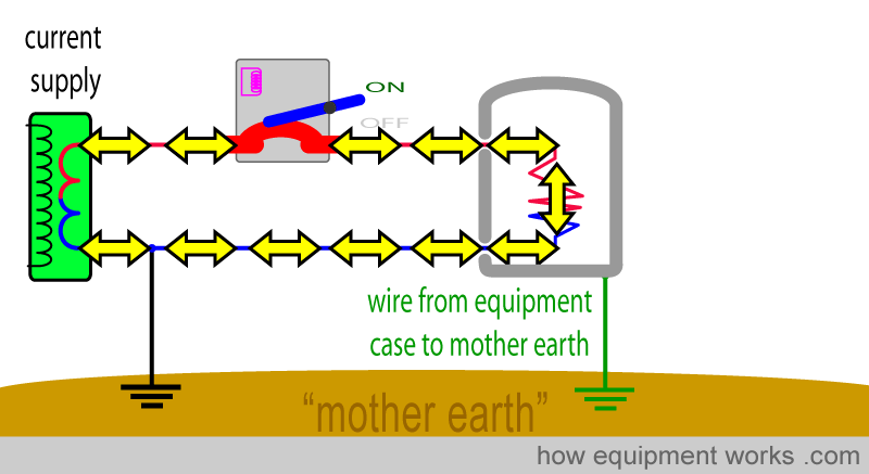
Now let us create an electrical fault.
The shock current goes to the equipment case and then goes to Mother Earth. This pathway has a very low resistance and therefore current can flow very easily. This leads to a very large current passing through the circuit breaker.
The high current makes the circuit breaker move into the OFF position and stops further current flow. Everything is now safe.
I would like you to note that the wire from the equipment casing to Mother Earth helps in two ways.
Firstly, it diverts the current away from the man.
Secondly, it makes a large current go through the circuit breaker which then makes it switch OFF.
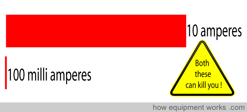
The above system protects you from only relatively large currents, such as 10 amperes. Unfortunately, currents that are much smaller than this, such as 100 milliamperes ( 100 times smaller than 10 amperes) can cause fatal ventricular fibrillation.
Therefore something that is more sensitive than fuses or circuit breakers is needed to protect you. I will now discuss one such device, which for now I will call an “unequal current stopper “. This can stop even small shock currents (e.g. less than 30 milli amperes).
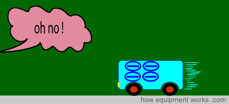
The “unequal current stopper ” works on the principle that what goes out must come back. Let me explain. Imagine that you are running a bus tour for tourists. You send six precious tourists (who have paid you a lot of money) on a tour.

The six tourists go on a long tour enjoying various sites.

And while you are thrilled to see them return, you discover that there is a big problem. Now there are only four tourists, instead of six!
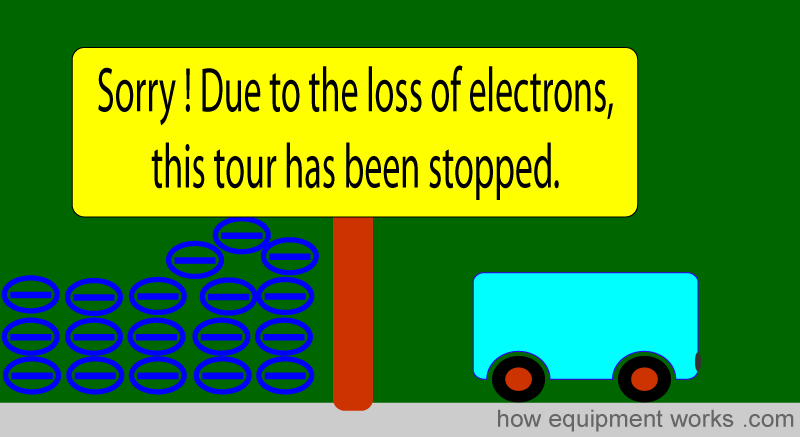
So what has happened? Clearly, you have lost two tourists. You don’t know where it has happened. All you know is that two are missing and must have fallen off somewhere.
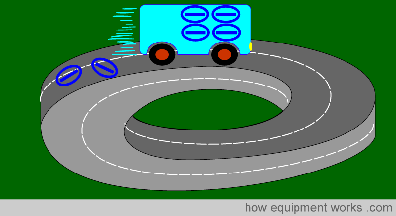
Now there are new tourists waiting to get into your bus for a tour. You of course stop any more tourists going because you know something is wrong. You don’t know where the missing tourists have gone, but you do know that they are getting lost somewhere. You know this because the number of tourists who return is less than the number who were there at the start of the tour. Since this is an unsafe situation and you are an honest tour operator, you shut down your tour service.
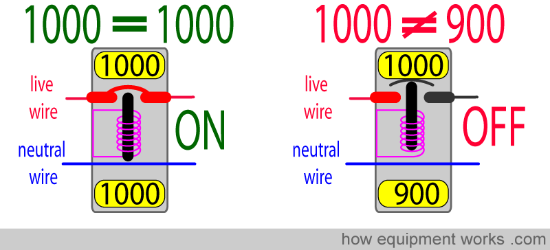
The “unequal current stopper ” works the same way. It continuously checks to see if the amount of current that goes to the equipment equals the amount of current that returns from the equipment. I.e. it compares the current flowing in the live wire and the current flowing in the neutral wire to see if they are equal. In the example below, 1000 milliamperes (1000 milliamperes = 1 ampere) are going to the equipment and 1000 milliamperes are returning from the equipment. Since the current in the live wire equals the current in the neutral wire, the unequal current stopper device remains ON and lets the current flow.
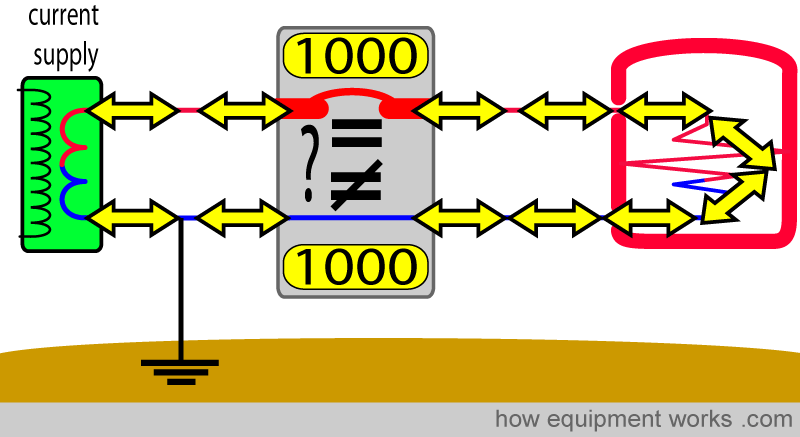
If there is a difference (i.e. it is not equal), as shown on the right below, it switches OFF and stops the current flow.
Now let us see how it can protect against an electric shock. Our man decides to touch the faulty equipment and is getting a shock. The shock current (30 milliamperes in the example below) goes through the man to Mother Earth and returns to the current supply WITHOUT going past the unequal current stopper (see red arrows). Therefore in the example below, while 1000 milliamperes is going through the unequal current stopper to the equipment, only 970 milliamperes returns back through it.
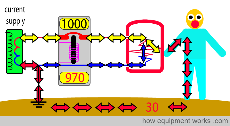
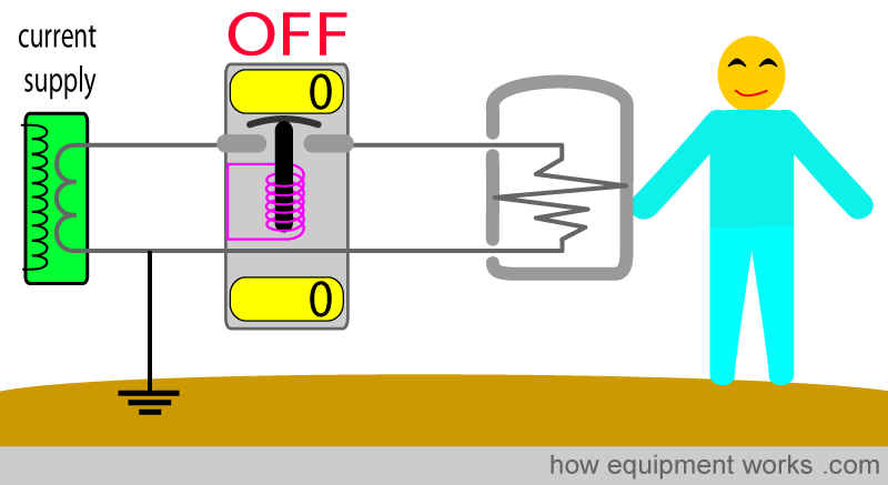
The current stopper detects the unequal current and immediately stops the current supply, making everything safe.
The unequal current stopper is capable of measuring very small differences (e.g. 30 milliamperes) and thus is able to offer good protection against even small but potentially lethal currents.
The “unequal current stopper ” is a name that I made up to make things easier to understand. In reality, depending on which country you are in, this device may be called: “Residual Current Device (RCD) “, “Residual Current Circuit Breaker “, “Ground Fault Circuit Interrupter (GFCI) “, “Ground Fault Interrupter (GFI) “, “Appliance Leakage Current or Interrupter (ALCI). “
Class 1 symbol:
At this point, let me introduce you to another electrical symbol that you may see. Electrical systems that use the equipment case to mother earth wire for protection are called “Class 1” equipment. You may see the symbol below in class 1 equipment.

Isolation transformer
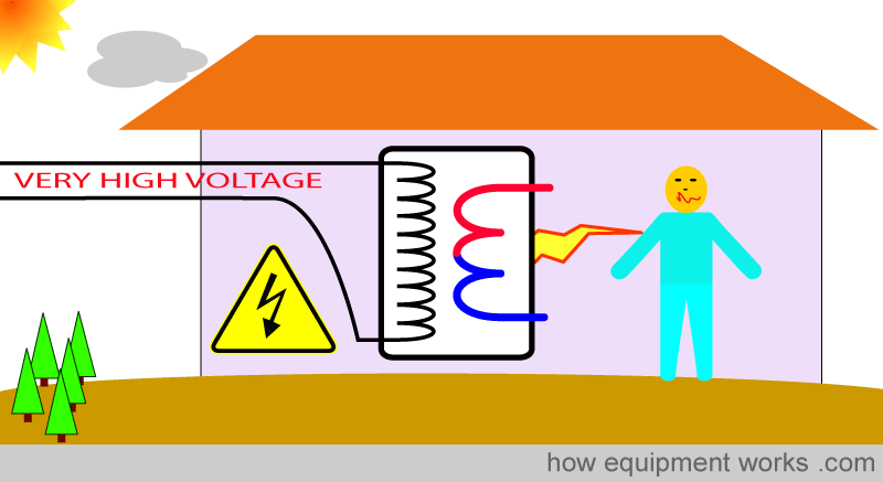
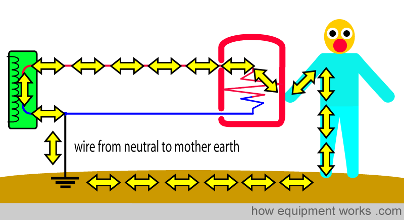
Look at the shock pathway, which you are now very familiar with. You will recall that the shock current returns to the source through the wire from neutral to Mother Earth.
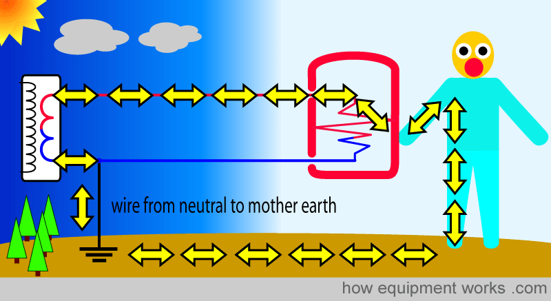
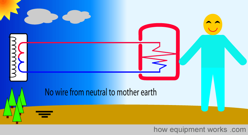
Let us for a moment imagine that there is no such thing as a “wire from neutral to Mother Earth”. Now, in the example below, even though the man is touching the faulty equipment, there is no way for the current to return back through him to the source. Because it can’t return home through the man, it doesn’t even enter him. Therefore he remains happily shock-free.
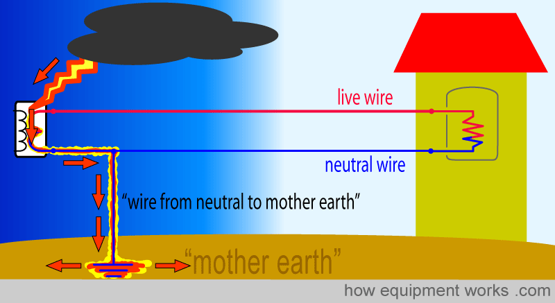
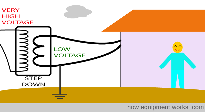
So if the electric company didn’t have a wire from neutral to Mother Earth, we would all be shock-free! But in reality, that is not possible. You will remember that the step-down transformer supplying current is susceptible to lightning strikes.
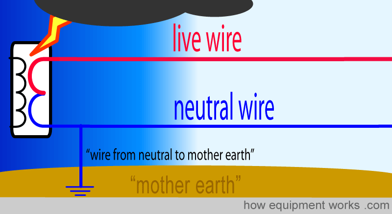
You will recall that the wire from neutral to Mother Earth is what diverts the dangerous lightning current safely to Mother Earth. Unfortunately, we therefore cannot get rid of the wire from neutral to Mother Earth.
However, there is a trick we can do to get rid of the wire from neutral to Mother Earth. We just discussed how, because the step-down transformer is outside, it is susceptible to lightning strikes and that is why we need the wire from neutral to Mother Earth. But what if we can have a transformer inside our hospital where it will be safe from such lightning strikes? Then we won’t need the wire from neutral to Mother Earth, and everyone will be happy! Unfortunately, that would not be advisable. The step-down transformer works with very high voltages which would present a hazard to those working inside the building.
So we move the step-down transformer back again to the outside, along with its wire from neutral to Mother Earth.
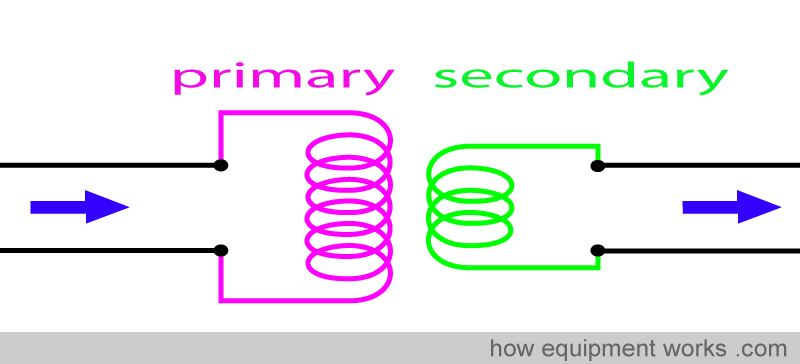
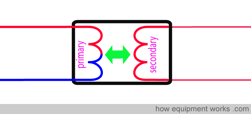
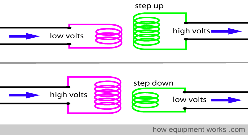
The solution to the problem is to install another transformer. However, before we proceed further, I need to remind you about how transformers work. Transformers are devices that can change the voltage of an AC current (more details were explained to you in the basic electricity section of this website). It consists of two coils. The coils consist of turns of wire. Current enters the transformer and goes to the “primary” coil. The current leaves the transformer from the “secondary” coil.
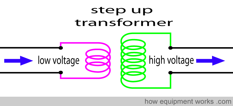
The ratio of the number of turns of wire on either side determines if the transformer raises or lowers the voltage. If the primary coil has fewer turns than the secondary coil, the transformer is called a step-up transformer. This type of transformer raises the voltage.
If the primary coil has more turns than the secondary coil, it is called a step-down transformer. Such a transformer reduces the voltage.
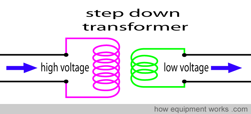
This type of transformer is often found outside your hospital. It reduces the high voltage used for long-distance power transmission to a lower safer voltage that is fed into your hospital.
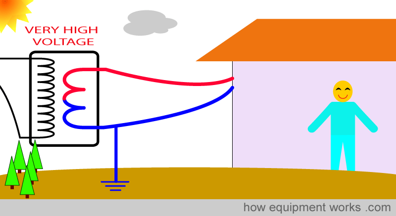
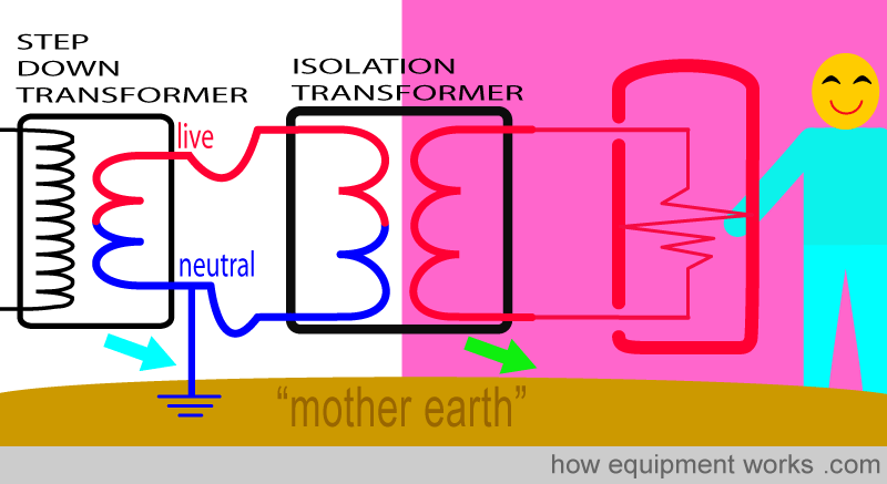
Now let us get back to trying to get rid of the wire from neutral to Mother Earth. For safety, as discussed before, we let the power company keep its step-down transformer well away from us. We also let them keep their wire from neutral to Mother Earth connected.
Now here is our solution. We install another transformer! This one, we safely keep inside our hospital. Because it is not exposed to lightning, it doesn’t have the problems of the transformer outside.
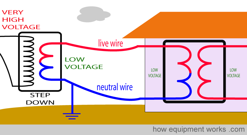
As you have seen, the step-down transformer outside has a wire from neutral to Mother Earth for safety (blue arrow). On the other hand, the second transformer we install is safely inside our hospital and therefore we do not need a ‘wire to Mother Earth’ for this transformer. (wire “absence” shown by green arrow) .
Look at the second transformer that we have inside our hospital. Note that there is a gap ( green arrow) between the coils. Therefore, there is no direct electrical connection between the two sides.
This gap prevents unwanted currents such as those due to shocks from going from one side to the other. In other words, this transformer “isolates” the circuit on one side (blue area) from the circuit on the other side (green area). Because of this, one can call this an “isolation transformer”.

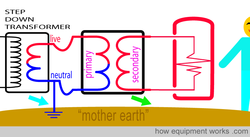
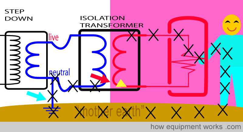
Now let us see how the isolation transformer protects us from shock. You will recall that without such a transformer, the shock current goes through the man and returns to the source by going through Mother Earth and the ‘wire from neutral to Mother Earth’.
Now let us have our faulty equipment connected to the isolation transformer. The case of the equipment is live with current and our man is touching it. However, he does not get a shock! This is because the current has no way of returning to the isolation transformer as there is no wire from neutral to Mother Earth (wire “absence” shown by green arrow).

You may wonder why the shock current couldn’t have returned through the ‘wire from neutral to mother earth’ of the step-down transformer (blue arrow). The reason this doesn’t happen is because the isolation transformer has divided the circuit into separate parts. The circuit in the pink part has no direct connection to the circuits in the “non-pink” parts. Shock current cannot travel from the pink part to the non-pink part.
Let me try and make things more clear. For our man to get an electric shock, the current has to be able to return to its source (isolation transformer with yellow triangle). This cannot happen because the isolation transformer does not have a wire from neutral to Mother Earth (green arrow).
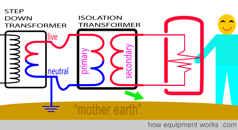
Now you may ask if the shock current (black Xs) can return to the source (yellow triangle) through the wire from neutral to mother earth (blue arrow) of the step-down transformer.
This does not happen because the isolation transformer prevents shock current from passing across from one side to the other (red arrow) to reach the source (yellow triangle). For this reason, our man remains shock-free!
As we have learnt before, transformers normally “transform” voltage to either lower or higher voltages.
However, most isolation transformers are different. They neither raise nor lower the voltage. They have the same number of turns of wire on the primary and secondary sides and therefore do not change (i.e. do not transform) the voltage. Nevertheless, we still call them transformers, because they look so similar to other transformers that change voltage.
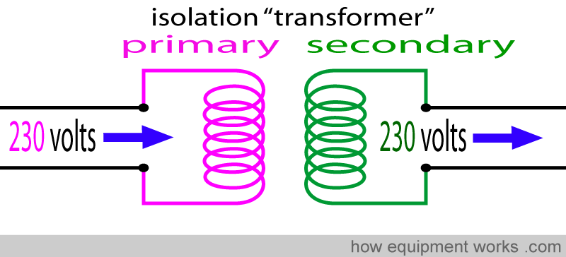
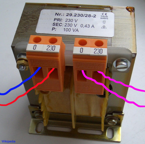
Below is a photograph of an isolation transformer. Note that the input voltage (230 volts) equals the output voltage (230 volts).
Please click the “Next” button below to read the final part about electrical safety. Thank you.